EVAL-AD9835EB Analog Devices Inc, EVAL-AD9835EB Datasheet - Page 5
EVAL-AD9835EB
Manufacturer Part Number
EVAL-AD9835EB
Description
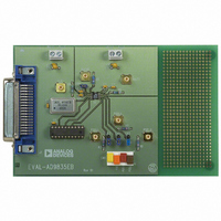
BOARD EVAL FOR AD9835
Manufacturer
Analog Devices Inc
Datasheet
1.EVAL-AD9835EB.pdf
(8 pages)
Specifications of EVAL-AD9835EB
Lead Free Status / RoHS Status
Contains lead / RoHS non-compliant


Features of the AD9835 Evaluation Board Software
The software allows the user to control all the functionality of
the AD9835. The main features are listed below.
• Access to both Frequency 0 and Frequency 1 registers
• Access to the Phase Reg. 0, Phase Reg. 1, Phase Reg. 2 and
• Access to Sleep, Reset and SELSRC bits.
• Ability to sweep through a frequency range using either the
Each of these features is described in detail in this application
note.
The Frequency Registers
The AD9835 contains 2 frequency registers which can be
programmed individually. The software allows the user to
enter any frequency value between 0Hz and half the master
clock frequency. If a value outside this range is entered the
software picks the closest valid value. The frequency value is
converted to a 32 bit hexidecimal number which is loaded to
the appropriate frequency register when the enter key is
pressed. The hexidecimal number is also displayed on the
main screen.
The Phase Registers
The AD9835 contains four phase register which can be
individually loaded with different values. The phase numbers
are entered as integer values between 0 and 4095 (corresponding
to 0° to 360° phase shift). Once again the values are loaded
to the appropriate phase register when the enter key is
pressed.
Normal/Sleep Mode
The Control Register of the AD9835 contains a sleep bit to
put the part into a power-down mode. When this bit is a logic
1 the internal clocks are disabled and the DAC's current
sources and REFOUT are turned off. This bit can be
controlled by the two radio buttons in the Normal/Sleep
Mode box. The software defaults to Normal Mode reflecting
the reset state of the AD9835.
Reset Mode
The Reset bit in the Control Register of the AD9835 is
controllable by the RESET button of the AD9835 Evaluation
Board Software. Pressing this button toggles the state of the
bit in the control register. Note that it is assummed that the
RESET bit is low when the software is started. Setting the
RESET bit to 1 will set the phase accumulator to zero phase
corresponding to a full scale output.
Phase Reg. 3
Frequency 0 or Frequency 1 registers.
- 5 -
The SELSRC Bit
The SELSRC bit of the AD9835 is used to control the
selection of the frequency and phase registers used to provide
the output. If this bit is a zero the frequency and phase
selection comes from FSELECT, PSEL0 and PSEL1 pins
respectively. If the bit is a 1 then the registers are selected by
software. Pressing the SELSRC button toggles this bit on the
AD9835 and also enables or disables changing the frequency
and phase registers from software as required.
It should be noted that since there is no readback facility on
the AD9835 it is not possible to determine the contents of any
register which has not been programmed by the software. For
this reason selecting a frequency or phase register which
hasn't been programmed may give an unpredicted output.
The Sweep Facility
Pressing the Sweep button displays a new screen which can be
used to program the AD9835 to produce a continuously
increasing or decreasing frequency sweep. The user has the
option of entering a start frequency, a stop frequency and a
step frequency. There is also the option of setting the delay
between steps and the number of time the sweep is to be
repeated. If the user were to enter the sweep values shown
below then the frequency outputs also shown below will be
generated. Note that if the frequency span is not an integer
multiple of the step frequency then the span from the second
last frequency to the last frequency will be such that the stop
frequency is the last frequency outputed to the AD9835.
Start Freq.
Stop Freq.
Step Freq.
Frequency Outputs:
Both Frequency Register 0 and Frequency Register 1 can be
loaded with seperate frequency, step, delay and loop
information but the output from the AD9835 will depend on
which frequency register is selected via the FSELECT pin.
If changing the frequency register is required then the user
should ensure that the SELSRC bit is zero before starting the
sweep.
Additional Information
Information about the current version of software can be
gathered from the About Screen (accessed by pressing the
About button on the main screen).
EVAL-AD9835EB
1.00000MHz
1.70000MHz
0.20000MH
1.00000MHz
1.20000MHz
1.40000MHz
1.60000MHz
1.70000MHz
Rev. A
Related parts for EVAL-AD9835EB
Image
Part Number
Description
Manufacturer
Datasheet
Request
R

Part Number:
Description:
ENERCHIP CC EVAL KIT
Manufacturer:
Cymbet Corporation
Datasheet:

Part Number:
Description:
BOARD EVAL FOR AD976
Manufacturer:
Analog Devices Inc
Datasheet:

Part Number:
Description:
BOARD EVAL FOR ADXL345
Manufacturer:
Analog Devices Inc
Datasheet:

Part Number:
Description:
ENERCHIP CC SEH EVAL KIT
Manufacturer:
Cymbet Corporation
Datasheet:

Part Number:
Description:
ENERCHIP EP ENERGY HARVEST EVAL
Manufacturer:
Cymbet Corporation
Datasheet:

Part Number:
Description:
EVAL BOARD FOR TW6864-LB2-GR
Manufacturer:
Intersil
Datasheet:
Part Number:
Description:
EVAL BOARD FOR TW8816-LB3-GR
Manufacturer:
Intersil
Datasheet:
Part Number:
Description:
EVAL BOARD FOR TW8817-TA3-GRS
Manufacturer:
Intersil
Datasheet:

Part Number:
Description:
EVALUATION MODULE FOR ADUM4160
Manufacturer:
Analog Devices Inc
Datasheet:

Part Number:
Description:
BOARD EVALUATION ADCMP581BCP
Manufacturer:
Analog Devices Inc
Datasheet:
Part Number:
Description:
BOARD EVALUATION ADM1041
Manufacturer:
Analog Devices Inc
Datasheet:

Part Number:
Description:
EVAL BOARD FOR STM32F107VCT
Manufacturer:
STMicroelectronics
Datasheet:
Part Number:
Description:
BOARD EVAL FOR AD1954
Manufacturer:
Analog Devices Inc
Datasheet:
Part Number:
Description:
BOARD EVAL FOR AD1955
Manufacturer:
Analog Devices Inc
Datasheet:

Part Number:
Description:
BOARD EVAL FOR AD7655
Manufacturer:
Analog Devices Inc
Datasheet: