EVAL-ADUC824QS Analog Devices Inc, EVAL-ADUC824QS Datasheet - Page 62
EVAL-ADUC824QS
Manufacturer Part Number
EVAL-ADUC824QS
Description
KIT DEV FOR ADUC824 QUICK START
Manufacturer
Analog Devices Inc
Series
QuickStart™ Kitr
Type
8052-corer
Datasheet
1.EVAL-ADUC824QSZ.pdf
(68 pages)
Specifications of EVAL-ADUC824QS
Contents
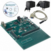
Evaluation Board, Power Supply, Cable, Software and Documentation
For Use With/related Products
ADuC824
Lead Free Status / RoHS Status
Contains lead / RoHS non-compliant


ADuC824
ADuC824 HARDWARE DESIGN CONSIDERATIONS
This section outlines some of the key hardware design consider-
ations that must be addressed when integrating the ADuC824
into any hardware system.
Clock Oscillator
As described earlier, the core clock frequency for the ADuC824
is generated from an on-chip PLL that locks onto a multiple
(384 times) of 32.768 kHz. The latter is generated from an inter-
nal clock oscillator. To use the internal clock oscillator, connect
a 32.768 kHz parallel resonant crystal between XTAL1 and
XTAL2 pins (32 and 33) as shown in Figure 43.
As shown in the typical external crystal connection diagram in
Figure 44, two internal 12 pF capacitors are provided on-chip.
These are connected internally, directly to the XTAL1 and
XTAL2 pins and the total input capacitances at both pins is
detailed in the specification section of this data sheet. The value
of the total load capacitance required for the external crystal
should be the value recommended by the crystal manufacturer
for use with that specific crystal. In many cases, because of the
on-chip capacitors, additional external load capacitors will not
be required.
External Memory Interface
In addition to its internal program and data memories, the
ADuC824 can access up to 64 Kbytes of external program memory
(ROM/PROM/etc.) and up to 16 Mbytes of external data
memory (SRAM).
To select from which code space (internal or external program
memory) to begin executing instructions, tie the EA (external
access) pin high or low, respectively. When EA is high (pulled up
to V
internal 8 Kbytes Flash/EE code space. When EA is low (tied to
ground) user program execution will start at address 0 of the
external code space. In either case, addresses above 1FFF hex
(8K) are mapped to the external space.
Note that a second very important function of the EA pin is
described in the Single Pin Emulation Mode section of this
data sheet.
External program memory (if used) must be connected to the
ADuC824 as illustrated in Figure 44. Note that 16 I/O lines
(Ports 0 and 2) are dedicated to bus functions during external
program memory fetches. Port 0 (P0) serves as a multiplexed
address/data bus. It emits the low byte of the program counter
(PCL) as an address, and then goes into a float state awaiting
the arrival of the code byte from the program memory. During the
DD
), user program execution will start at address 0 of the
32.768kHz
XTAL1
XTAL2
12pF
12pF
ADuC824
TO INTERNAL
PLL
time that the low byte of the program counter is valid on P0, the
signal ALE (Address Latch Enable) clocks this byte into an
address latch. Meanwhile, Port 2 (P2) emits the high byte of
the program counter (PCH), then PSEN strobes the EPROM
and the code byte is read into the ADuC824.
Note that program memory addresses are always 16 bits wide, even
in cases where the actual amount of program memory used is less
than 64 Kbytes. External program execution sacrifices two of the
8-bit ports (P0 and P2) to the function of addressing the program
memory. While executing from external program memory, Ports
0 and 2 can be used simultaneously for read/write access to exter-
nal data memory, but not for general-purpose I/O.
Though both external program memory and external data memory
are accessed by some of the same pins, the two are completely
independent of each other from a software point of view. For
example, the chip can read/write external data memory while
executing from external program memory.
Figure 45 shows a hardware configuration for accessing up to
64 Kbytes of external RAM. This interface is standard to any 8051
compatible MCU.
If access to more than 64 Kbytes of RAM is desired, a feature
unique to the ADuC824 allows addressing up to 16 Mbytes
of external RAM simply by adding an additional latch as illustrated
in Figure 46.
ADuC824
ADuC824
PSEN
ALE
ALE
WR
RD
P2
P2
P0
P0
LATCH
LATCH
OE
OE
WE
D0–D7
(INSTRUCTION)
A0–A7
A8–A15
D0–D7
(DATA)
A0–A7
A8–A15
EPROM
SRAM
Related parts for EVAL-ADUC824QS
Image
Part Number
Description
Manufacturer
Datasheet
Request
R


Part Number:
Description:
BOARD EVAL FOR SI270X-A
Manufacturer:
Silicon Laboratories Inc
Datasheet:

Part Number:
Description:
BUCK CONV REF DESIGN KIT IP1201
Manufacturer:
International Rectifier
Datasheet:
Part Number:
Description:
BOARD DEMO SYNC DUAL BUCK CNVTER
Manufacturer:
International Rectifier
Datasheet:
Part Number:
Description:
BOARD DEMO SYNC BUCK CONVETER
Manufacturer:
International Rectifier
Datasheet:

Part Number:
Description:
EVALBOARD/EB Omnidirectional microphone - Analog
Manufacturer:
Analog Devices
Datasheet:
Part Number:
Description:
EVALBOARD/EB Omnidirectional microphone - Analog
Manufacturer:
Analog Devices
Datasheet:


Part Number:
Description:
BOARD EVAL LED DRIVER LT3756
Manufacturer:
Linear Technology
Datasheet:

Part Number:
Description:
BOARD EVAL FOR AD7741/7742
Manufacturer:
Analog Devices Inc
Datasheet:

Part Number:
Description:
±1.7g Dual-Axis IMEMS Accelerometer Evaluation Board
Manufacturer:
Analog Devices Inc
Datasheet:

Part Number:
Description:
IC MULTIPLIER ANALOG 8-SOIC T/R
Manufacturer:
Analog Devices Inc
Datasheet:

Part Number:
Description:
IC ANALOG MULTIPLIER 8-DIP
Manufacturer:
Analog Devices Inc
Datasheet:
Part Number:
Description:
IC ANALOG MULTIPLIER 8-SOIC
Manufacturer:
Analog Devices Inc
Datasheet:
Part Number:
Description:
IC ANALOG MULTIPLIER 8-DIP
Manufacturer:
Analog Devices Inc
Datasheet: