DB64 Cirrus Logic Inc, DB64 Datasheet

DEMO BOARD FOR SA306-IHZ

DB64

Manufacturer Part Number
DB64
Description
DEMO BOARD FOR SA306-IHZ
Manufacturer
Cirrus Logic Inc
Series
Apex Precision Power™r
Type
MOSFET & Power Driverr
Datasheets

Specifications of DB64

Main Purpose
Power Management, Motor Control
Embedded
No
Utilized Ic / Part
SA306
Primary Attributes
3-Ph DC Motors
Secondary Attributes
12V Supply, 1kW Peak Power, 17A Peak Current, Board can Dissipate 7-9W
Input Voltage
5 V
Board Size
95.25 mm x 44.45 mm
Maximum Operating Temperature
+ 70 C
Minimum Operating Temperature
0 C
Product
Power Management Modules
Dimensions
95.25 mm x 44.45 mm
For Use With/related Products
SA306-IHZ
Lead Free Status / RoHS Status
Contains lead / RoHS non-compliant
Lead Free Status / RoHS Status
Lead free / RoHS Compliant, Contains lead / RoHS non-compliant
Other names
598-1488
INTRODUCTION
The DB64 is designed to demonstrate the capabilities of the SA306 3 phase brushless DC (BLDC) motor driver IC.
This fully assembled demonstration allows the user to directly control the speed and direction of the motor. An on-
board controller decodes HALL Effect sensor inputs for commutation in either direction and provides four quadrant
PWM signals to control the power outputs of the SA306. LEDs provide feedback for motor control status and fault
indications. Provisions on the DB64 allow the user to bypass the onboard control circuit and directly interface with
the SA306 brushless motor driver.
The DB64 demonstrates proper layout techniques for the
SA306 high current switching amplifier. The economical con-
struction uses only a two-sided PCB and allows the SA306
to deliver peak currents of over 1kW.
THERMAL CONSIDERATIONS
The SA306 is available in a surface mount package which
can deliver peak power of over 1kW. This presents an obvi-
ous and significant thermal challenge. The DB64 offers a
compact design which can deliver 17A peak current by using
a patent pending mounting technique. Mounting the SA306
in an inverted fashion as shown in Figure 1 reduces the pro-
file height of the assembly and provides a direct interface be-
tween the thermal tab of the PowerQuad package (package
outline drawing HQ) and the small HS33 heatsink. The DB64
assembly can dissipate 7-9W in still air at 25ºC ambient tem-
perature, depending on the orientation of the heatsink fins.
To use the DB64 in higher power applications, use a fan or
mount a heatsink with larger thermal mass. Although the
SA306 is rated for operation from -25 to +85ºC, the other
components on the DB64 are limited to 0 to 70ºC ambient
temperature.
CIRCUIT OPERATION
The DB64 control circuit receives power via two terminal
block connections. The Vs connection supplies power to
drive the motor and must be above the under-voltage lock-
out threshold of the SA306, approximately 8.3V. The control
circuit requires 12V for proper operation a regulator on the
DB64 provides the 5V logic supply for the SA306. There are
no special considerations for sequencing the two supplies.
DB64U
http://www.cirrus.com
Demonstration Board for the SA306-IHZ
P r o d u c t I n n o v a t i o n F r o m
Copyright © Cirrus Logic, Inc. 2008
(All Rights Reserved)
Figure 1 – Mounting Technique
PaTenT PenDing
APEX − DB64UREVA
DB64
OCT 2008
DB64


Related parts for DB64

DB64 Summary of contents

Page 1

... Demonstration Board for the SA306-IHZ INTRODUCTION The DB64 is designed to demonstrate the capabilities of the SA306 3 phase brushless DC (BLDC) motor driver IC. This fully assembled demonstration allows the user to directly control the speed and direction of the motor. An on- board controller decodes HALL Effect sensor inputs for commutation in either direction and provides four quadrant PWM signals to control the power outputs of the SA306 ...

Page 2

... SA306. Push-button switches 1 and 2 trigger latches (U4) for direction and enable con- trol, respectively. Diodes D7 & D8 and resistors R24, 25, 29 & 30 provide a means of bypassing the DB64 control circuit. The 5V regulator, U3, provides 5V to the SA306, the latches and the status LEDs. ...

Page 3

... Connector J4 is connected directly to the PWM input pins of the SA306. This connector may be used to monitor the signals or to bypass the control IC on the DB64. The enable function is not controlled via these pins, although pulling all six input pins low provides the same effect. The Enable pushbutton and the connection via J5 are also effective as previously described ...

Page 4

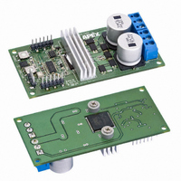
... Figure 4 shows the top and bottom layouts of the DB64. Gerber files for the circuit board are available upon re- quest. Figure 4 – PCB Layout (not to scale) ...

Page 5

... R29,R30 R4,R5,R6,R18,R19,R20,R21,R32 R7,R31 R8 R9,R10,R14,R15,R16,R17,R22,R23 SW1,SW2 TB1,TB2 Thermal Grease ORDERING INFORMATION DB64 Demonstration Board includes one populated EVAL67 PCB and one SA306-IHZ sample DB64U Description P/N CAP, 1.0uF, 16V Kemet, C0805C105K4RAC CAP, 33pF, 16V Kemet C0603C330J5GACTU CAP, 1.0nF,100V Kemet,C0805C102J1GACTU CAP, 150uF, 100V Panasonic, EEVFK2A151M CAP, 0 ...

Page 6

... LIABILITY, INCLUDING ATTORNEYS’ FEES AND COSTS, THAT MAY RESULT FROM OR ARISE IN CONNECTION WITH THESE USES. Cirrus Logic, Cirrus, and the Cirrus Logic logo designs, Apex and Apex Precision Power are trademarks of Cirrus Logic, Inc. All other brand and product names in this document may be trademarks or service marks of their respective owners. 6 DB64U ...

Related keywords