DB64 Cirrus Logic Inc, DB64 Datasheet - Page 2
DB64
Manufacturer Part Number
DB64
Description
DEMO BOARD FOR SA306-IHZ
Manufacturer
Cirrus Logic Inc
Series
Apex Precision Power™r
Type
MOSFET & Power Driverr
Specifications of DB64
Main Purpose
Power Management, Motor Control
Embedded
No
Utilized Ic / Part
SA306
Primary Attributes
3-Ph DC Motors
Secondary Attributes
12V Supply, 1kW Peak Power, 17A Peak Current, Board can Dissipate 7-9W
Input Voltage
5 V
Board Size
95.25 mm x 44.45 mm
Maximum Operating Temperature
+ 70 C
Minimum Operating Temperature
0 C
Product
Power Management Modules
Dimensions
95.25 mm x 44.45 mm
For Use With/related Products
SA306-IHZ
Lead Free Status / RoHS Status
Contains lead / RoHS non-compliant
Lead Free Status / RoHS Status
Lead free / RoHS Compliant, Contains lead / RoHS non-compliant
Other names
598-1488


DB64
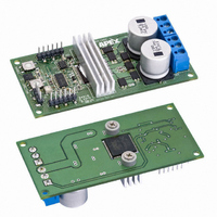
Figure 2 shows the user control features of the DB64. The
PWM duty cycle is controlled with the potentiometer (1
in figure 2). The power LED (2) will illuminate when the
12V supply is connected. The DB64 will power up with
the SA306 disabled. The enable button (3) will toggle the
SA306 on and off with the LED (4) illuminating to indi-
cate the enable status. Direction of the motor is similarly
controlled with the button (5) and is indicated by the LED
(6).
The DB64 monitors the Temperature warning status pin
of the SA306. If this pin goes high an LED (7) illuminates
and the enable circuit is forced to a disable status. The
temperature LED is not latched and may stay illuminated
only briefly while the temperature of the SA306 is above
135ºC. The temperature decrease rapidly via the heatsink
once the SA306 is disabled.
The SA306 current limit feature is set to limit at approxi-
mately 15A to provide a demonstration of the full capabili-
ties of the SA306. An LED (8) will illuminate if the SA306
cycle-by-cycle current limit circuit engages. The thermal
and current limit features are robust, but will not protect
the SA306 in all circumstances. The user must consider the worst case thermal and power dissipation conditions.
Hall Effect inputs to connector J3 (9) are required to commutate the motor correctly. Filtering networks and 5V pull-
up are provided for glitch-free operation. The Hall sensor connector, J3 (9), also includes a tachometer output which
is based on the commutation signals from the Hall inputs. Power for the Hall sensors is provided by U2 in figure 3,
an integrated brushless motor controller IC. The controller decodes the Hall sensor inputs and generates six PWM
control signals directly to the SA306. Push-button switches 1 and 2 trigger latches (U4) for direction and enable con-
trol, respectively. Diodes D7 & D8 and resistors R24, 25, 29 & 30 provide a means of bypassing the DB64 control
circuit. The 5V regulator, U3, provides 5V to the SA306, the latches and the status LEDs.
2
P r o d u c t I n n o v a t i o n F r o m
Figure 2 – User Control Features
3
5
4
6
10
1
11
9
2
7
8
DB64U
Related parts for DB64
Image
Part Number
Description
Manufacturer
Datasheet
Request
R

Part Number:
Description:
Development Kit
Manufacturer:
Cirrus Logic Inc
Datasheet:
Part Number:
Description:
Development Kit
Manufacturer:
Cirrus Logic Inc
Datasheet:


Part Number:
Description:
High-efficiency PFC + Fluorescent Lamp Driver Reference Design
Manufacturer:
Cirrus Logic Inc
Datasheet:
Part Number:
Description:
Development Kit
Manufacturer:
Cirrus Logic Inc
Datasheet:
Part Number:
Description:
Development Kit
Manufacturer:
Cirrus Logic Inc
Datasheet:

Part Number:
Description:
Development Kit
Manufacturer:
Cirrus Logic Inc
Datasheet:
Part Number:
Description:
Development Kit
Manufacturer:
Cirrus Logic Inc
Datasheet:
Part Number:
Description:
Development Kit
Manufacturer:
Cirrus Logic Inc
Datasheet:
Part Number:
Description:
Development Kit
Manufacturer:
Cirrus Logic Inc
Datasheet:

Part Number:
Description:
EVALUATION BOARD FOR CS8427
Manufacturer:
Cirrus Logic Inc
Datasheet:

Part Number:
Description:
BOARD EVAL FOR CS8416 RCVR
Manufacturer:
Cirrus Logic Inc
Datasheet:

Part Number:
Description:
EVALUATION BOARD FOR CS8420
Manufacturer:
Cirrus Logic Inc
Datasheet:

Part Number:
Description:
KIT DEVELOPMENT EP9315 ARM9
Manufacturer:
Cirrus Logic Inc
Datasheet:

Part Number:
Description:
KIT DEVELOPMENT EP9302 ARM9
Manufacturer:
Cirrus Logic Inc
Datasheet: