DB64 Cirrus Logic Inc, DB64 Datasheet - Page 3
DB64
Manufacturer Part Number
DB64
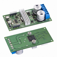
Description
DEMO BOARD FOR SA306-IHZ
Manufacturer
Cirrus Logic Inc
Series
Apex Precision Power™r
Type
MOSFET & Power Driverr
Specifications of DB64
Main Purpose
Power Management, Motor Control
Embedded
No
Utilized Ic / Part
SA306
Primary Attributes
3-Ph DC Motors
Secondary Attributes
12V Supply, 1kW Peak Power, 17A Peak Current, Board can Dissipate 7-9W
Input Voltage
5 V
Board Size
95.25 mm x 44.45 mm
Maximum Operating Temperature
+ 70 C
Minimum Operating Temperature
0 C
Product
Power Management Modules
Dimensions
95.25 mm x 44.45 mm
For Use With/related Products
SA306-IHZ
Lead Free Status / RoHS Status
Contains lead / RoHS non-compliant
Lead Free Status / RoHS Status
Lead free / RoHS Compliant, Contains lead / RoHS non-compliant
Other names
598-1488


DB64
P r o d u c t I n n o v a t i o n F r o m
Figure 3 – Schematic
ENHANCING & BYPASSING THE DB64 CONTROL CIRCUIT
Connector J5 allows the user to bypass many of the manual control features of the DB64. A signal generator can
control the duty cycle with a 2.5 to 7.5V signal, overriding the control potentiometer. A rising 5V edge on pin 3 or 4 of
connector J5 will toggle the Direction or Enable latches, respectively. By jumping resistors R24 & R25, the latches
are bypassed completely and the logic signals on pins 3 & 4 will directly control the direction and enable functions
of the DB64. With these resistors jumped, the direction and enable LEDs will not represent the states of the DB64
and the pushbuttons will have no effect on the operation. The Temperature disable feature of the DB64 will also not
function, although the LED will continue to provide over-temperature status.
Connector J4 is connected directly to the PWM input pins of the SA306. This connector may be used to monitor the
signals or to bypass the control IC on the DB64. The enable function is not controlled via these pins, although pulling
all six input pins low provides the same effect. The Enable pushbutton and the connection via J5 are also effective
as previously described. The circuit shown in figure 3 in the dashed box is a simple circuit that allows the user to
monitor and control the enable or direction status remotely. Either feature can be toggled on the falling edge of the
signal at the node labeled TOGGLE.
LAYOUT CONSIDERATIONS
A simple two layer construction is sufficient because of the convenient pinout of the SA306 PowerQuad package.
Input signals are routed into one side of the package and high power output signals are routed from the other side in
2 ounce copper. This eliminates the need to route control signals near motor connections where noise may corrupt
the signals. Filling top and bottom layers with copper reduces inductive coupling from the high current outputs. 1nF
capacitors with excellent high frequency characteristics bypass the Vs motor supplies on each phase. Two 150μF
DB64U
Related parts for DB64
Image
Part Number
Description
Manufacturer
Datasheet
Request
R

Part Number:
Description:
Development Kit
Manufacturer:
Cirrus Logic Inc
Datasheet:
Part Number:
Description:
Development Kit
Manufacturer:
Cirrus Logic Inc
Datasheet:


Part Number:
Description:
High-efficiency PFC + Fluorescent Lamp Driver Reference Design
Manufacturer:
Cirrus Logic Inc
Datasheet:
Part Number:
Description:
Development Kit
Manufacturer:
Cirrus Logic Inc
Datasheet:
Part Number:
Description:
Development Kit
Manufacturer:
Cirrus Logic Inc
Datasheet:

Part Number:
Description:
Development Kit
Manufacturer:
Cirrus Logic Inc
Datasheet:
Part Number:
Description:
Development Kit
Manufacturer:
Cirrus Logic Inc
Datasheet:
Part Number:
Description:
Development Kit
Manufacturer:
Cirrus Logic Inc
Datasheet:
Part Number:
Description:
Development Kit
Manufacturer:
Cirrus Logic Inc
Datasheet:

Part Number:
Description:
EVALUATION BOARD FOR CS8427
Manufacturer:
Cirrus Logic Inc
Datasheet:

Part Number:
Description:
BOARD EVAL FOR CS8416 RCVR
Manufacturer:
Cirrus Logic Inc
Datasheet:

Part Number:
Description:
EVALUATION BOARD FOR CS8420
Manufacturer:
Cirrus Logic Inc
Datasheet:

Part Number:
Description:
KIT DEVELOPMENT EP9315 ARM9
Manufacturer:
Cirrus Logic Inc
Datasheet:

Part Number:
Description:
KIT DEVELOPMENT EP9302 ARM9
Manufacturer:
Cirrus Logic Inc
Datasheet: