TOOLSTICK912UPP Silicon Laboratories Inc, TOOLSTICK912UPP Datasheet - Page 12
TOOLSTICK912UPP
Manufacturer Part Number
TOOLSTICK912UPP
Description
ADAPTER PROGRAM TOOLSTICK F91X
Manufacturer
Silicon Laboratories Inc
Series
ToolStickr
Type
Microcontroller Programmerr
Specifications of TOOLSTICK912UPP
Contents
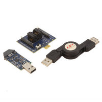
Base Adapter, C8051F330 Daughter Card and USB Cable
Processor To Be Evaluated
C8051F912
Processor Series
C8051F9xx
Interface Type
USB
Operating Supply Voltage
2.7 V to 3.6 V
Lead Free Status / RoHS Status
Contains lead / RoHS non-compliant
For Use With/related Products
C8051F91x/0x QSOP
Lead Free Status / Rohs Status
Lead free / RoHS Compliant
Other names
336-1867


ToolStick-F 91 2DC
7.4. Viewing and Modifying Registers
All registers on the device can be viewed and modified when the device is in a halted state. The registers are
grouped together according to which peripheral or part of hardware they belong. As an example, this guide shows
how to open the ADC0 Debug Window and disable the ADC0 directly from the IDE.
1. Open the ADC0 Debug Window from the View Debug Windows SFR’s ADC0 menu option. The
2. In the debug window, change the value of ADC0CN from 0x82 to 0x02. This value turns off the ADC on the
3. To write this new value to the device, select Refresh from the Debug Menu or click the Refresh button in the
4. Click “Go” to resume running the device with the new ADC0CN value.
5. Turn the potentiometer on the daughter card and notice that it has no effect on the blinking rate of the LED.
6. Re-enable the ADC by writing 0x82 to the ADC0CN and clicking the Refresh button.
12
ADC0 Debug Window appears on the right-hand side of the IDE. In this window, the ADC0CN register is shown.
This register is used to enable and configure the on-chip ADC. When the firmware is running, the ADC0CN
register reads as 0x82 indicating that the ADC is running.
target microcontroller.
toolbar.
Rev. 0.1
Related parts for TOOLSTICK912UPP
Image
Part Number
Description
Manufacturer
Datasheet
Request
R

Part Number:
Description:
KIT TOOL EVAL SYS IN A USB STICK
Manufacturer:
Silicon Laboratories Inc
Datasheet:

Part Number:
Description:
TOOLSTICK DEBUG ADAPTER
Manufacturer:
Silicon Laboratories Inc
Datasheet:

Part Number:
Description:
TOOLSTICK BASE ADAPTER
Manufacturer:
Silicon Laboratories Inc
Datasheet:

Part Number:
Description:
TOOLSTICK DAUGHTER CARD
Manufacturer:
Silicon Laboratories Inc
Datasheet:

Part Number:
Description:
TOOLSTICK DAUGHTER CARD
Manufacturer:
Silicon Laboratories Inc
Datasheet:

Part Number:
Description:
TOOLSTICK DAUGHTER CARD
Manufacturer:
Silicon Laboratories Inc
Datasheet:

Part Number:
Description:
TOOLSTICK DAUGHTER CARD
Manufacturer:
Silicon Laboratories Inc
Datasheet:

Part Number:
Description:
KIT STARTER TOOLSTICK
Manufacturer:
Silicon Laboratories Inc
Datasheet:

Part Number:
Description:
KIT UNIVERSITY TOOLSTICK STARTER
Manufacturer:
Silicon Laboratories Inc
Datasheet:

Part Number:
Description:
DAUGHTER CARD TOOLSTICK F330
Manufacturer:
Silicon Laboratories Inc
Datasheet:

Part Number:
Description:
CARD DAUGHTER UNIVRSTY TOOLSTICK
Manufacturer:
Silicon Laboratories Inc
Datasheet:

Part Number:
Description:
DAUGHTER CARD TOOLSTICK F582
Manufacturer:
Silicon Laboratories Inc
Datasheet:

Part Number:
Description:
DAUGHTER CARD TOOLSTICK F500
Manufacturer:
Silicon Laboratories Inc
Datasheet:

Part Number:
Description:
DAUGHTER CARD TOOLSTICK F540
Manufacturer:
Silicon Laboratories Inc
Datasheet:

Part Number:
Description:
DAUGHTER CARD TOOLSTICK F560
Manufacturer:
Silicon Laboratories Inc
Datasheet: