LD4T06P0 Red Lion Controls, LD4T06P0 Datasheet

TIMER 6 DIGIT 4.0" 120VAC RED

LD4T06P0

Manufacturer Part Number
LD4T06P0
Description
TIMER 6 DIGIT 4.0" 120VAC RED
Manufacturer
Red Lion Controls
Series
LDr
Type
Timerr
Datasheets

Specifications of LD4T06P0

No. Of Digits / Alpha
6
Digit Height
101mm
Power Consumption
26VA
Operating Temperature Range
0°C To +50°C
Signal Input Type
Pulse
Character Size
4"
Ip/nema Rating
IP65 / NEMA 4X
Signal Output Type
Relay
Accuracy
±0.01% %
Connection Type
Wire Leads
Dimensions
26"L×2.25"W×7.875"H
Display Digit Height
4 "
Display Resolution
0.001 Sec. (Minimum Digit), 1 hr. (Single Digit)
Display Type
LED
Function
Timer
Material, Casing
Aluminum
Number Of Digits
6
Primary Type
Electronic
Range, Measurement
0 to 999999
Special Features
RS485/RS232 Communications
Termination
Terminal Block
Voltage, Supply
85 to 250/11 to 16 VAC/VDC
Supply Voltage Range
21.6V DC To 250V DC
Count Speed Max
10Hz
External Depth
57.15mm
External Length / Height
200mm
Rohs Compliant
Yes
Counter Supply Voltage
85-250VAC/11-16VDC
Display Font Color
Red
Lead Free Status / RoHS Status
Lead free / RoHS Compliant
Lead Free Status / RoHS Status
Lead free / RoHS Compliant, Lead free / RoHS Compliant
Other names
RLC125
Tel +1 (717) 767-6511
Fax +1 (717) 764-0839
www.redlion.net
GENERAL DESCRIPTION
functions as an Elapsed Timer or Preset Timer, with full-featured user
programmability. The meter includes a built-in Cycle Counter, relay output and
serial communications capability. The 6 digit displays are available in either
2.25" or 4" high red LED digits with adjustable display intensity. The 2.25" high
models are readable up to 130 feet. The 4" high models are readable up to 180
feet. Both versions are constructed of a NEMA 4X/IP65 enclosure in light
weight aluminum.
modes provide level active or edge triggered start/stop operation. The Timer
features 18 selectable timer ranges to cover a wide variety of timing applications.
The built-in Cycle Counter can be linked to timer operation to count timing
cycles, or function as a totally independent counter, accepting count speeds up
to 500 Hz. The display can be toggled either manually or automatically between
the Timer and Counter values.
provided to perform a variety of meter functions. DIP switches are used to
configure the inputs for current sinking (active low) or current sourcing (active
high) operation.
configured to suit a variety of control and alarm requirements. The meter also
includes RS232 or RS485 serial communications.
MODEL LD - LARGE DISPLAY TIMER AND CYCLE COUNTER
DIMENSIONS In inches (mm)
The Large Display Timer and Cycle Counter is a versatile display that
The Timer has two signal inputs and eight input operating modes. These
In addition to the Timer/Counter inputs, a programmable User Input is
The Setpoint Output can be assigned to the Timer or Counter value, and
installation and operation of the unit.
Read complete instructions prior to
CAUTION: Risk of Danger.
AIR PRESSURE STABILIZATION VENT
CAUTION: Risk of electric shock.
X
Z
C C
U L
R
US LISTED
US LISTED
IND. CONT. EQ.
51EB
1
SAFETY SUMMARY
corresponding literature, or on equipment, must be observed to ensure personal
safety and to prevent damage to either the instrument or equipment connected to
it. If equipment is used in a manner not specified by the manufacturer, the
protection provided by the equipment may be impaired.
not equipped with safeguards. To do so can be potentially harmful to persons or
equipment in the event of a fault to the unit.
SPECIFICATIONS
1. DISPLAY: 2.25" (57 mm) or 4" (101 mm) intensity adjustable Red LED
2. POWER REQUIREMENTS:
3. TIMER DISPLAY: 6-digits
4. CYCLE COUNTER DISPLAY: 5-digits, may be disabled if not used
 2.25" or 4" HIGH RED LED DIGITS
 6-DIGIT BI-DIRECTIONAL TIMING CAPABILITY
 5-DIGIT CYCLE COUNTING CAPABILITY
 SELECTABLE TIMER RANGES AND OPERATING MODES
 ELAPSED TIMER AND PRESET TIMER FUNCTIONALITY
 SERIAL COMMUNICATIONS (RS232 or RS485)
 PROGRAMMABLE USER INPUT
 UNIVERSALLY POWERED
 5 AMP FORM C RELAY OUTPUT
 ALUMINUM NEMA 4X CASE CONSTRUCTION
All safety regulations, local codes and instructions that appear in this and
Do not use this unit to directly command motors, valves, or other actuators
AC POWER: 50 to 250 VAC 50/60 Hz, 26 VA
DC POWER: 21.6 to 250 VDC, 11 W
DC Out: +24 VDC @ 100 mA if input voltage is greater than 50 VAC/VDC
Isolation: 2300 V
Display Range: 0 to 999999
Overflow/Underflow Indication: Display flashes “
Minimum Digit Resolution: 0.001 Sec.
Maximum Single Digit Resolution: 1 Hr.
Timing Accuracy: ±0.01%
Display Designator: “
Display Range: 0 to 99999
Overflow/Underflow Indication: Display flashes “
+24 VDC @ 50 mA if input voltage is less than 50 VDC
Y
The protective conductor terminal is bonded to conductive
parts of the equipment for safety purposes and must be
connected to an external protective earthing system.
RMS
(57.15)
2.25
for 1 min. to all inputs and outputs
” to the left side of the display
LD2T06P0 16 (406.4) 4 (101.6)
LD4T06P0 26 (660.4) 7.875 (200) 22 (558.8)
NUMBER
PART
X (Length)


Y (Height)
Bulletin No. LDT-F
Drawing No. LP0634
Released 09/10
12 (304.8)
Z (Center)

Related parts for LD4T06P0

LD4T06P0 Summary of contents

Page 1

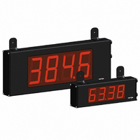
... PART X (Length) Y (Height) NUMBER Y LD2T06P0 16 (406.4) 4 (101.6) LD4T06P0 26 (660.4) 7.875 (200) 22 (558.8) 2.25 (57.15) Bulletin No. LDT-F Drawing No. LP0634 Released 09/10 ” ” Z (Center) 12 (304.8) ...

Page 2

... Meets NEMA 4X/IP65 specifications. Installation Category II, Pollution Degree 2. 14. WEIGHT: LD2T06P0 - 4.5 lbs (2.04 kg) LD4T06P0 - 10.5 lbs (4.76 kg) DESCRIPTION 2.25" High 6-Digit Red LED Timer/Cycle Counter w/ Relay Output & RS232/RS485 Serial Communications 4" ...

Page 3

... M ETER 4. Signal or Control cables within an enclosure should be routed as far as possible from contactors, control relays, transformers, and other noisy components extremely high EMI environments, the use of external EMI suppression devices, such as ferrite suppression cores, is effective. Install them on Signal and Control cables as close to the unit as possible. Loop the cable through the core several times or use multiple cores on each cable for additional protection ...

Page 4

WIRING OVERVIEW Electrical connections are made via pluggable terminal blocks located inside the meter. All conductors should conform to the meter's voltage and current ratings. All cabling should conform to appropriate standards of good installation, local codes and regulations. It ...

Page 5

INPUT WIRING The Large Display Timer is equipped with two signal inputs, A and B. These inputs are wired using the six position terminal block (TBB) located inside the unit on the right side. CAUTION: DC common is NOT ...

Page 6

R EVIEWING THE KEY DISPLAY MODE OPERATION PAR Access Programming Mode Select display (Timer or Cycle Counter) SEL RST Reset value(s) per front panel reset setting OPERATING MODE DISPLAY DESIGNATORS  “ ” the left of the ...

Page 7

... DAY Provides a 50 msec software debounce for the Timer Inputs (A and B). Select MAXIMUM DISPLAY  when using relays or switch contacts as a signal source. DISPLAY RESOLUTION    1 SEC     ...

Page 8

TIMER RESET AT POWER-UP         The Timer can be programmed to Reset at each meter power-up. USER INPUT FUNCTION     DISPLAY MODE DESCRIPTION  No Function User Input disabled. See ...

Page 9

MODULE PAR Front Panel Front Panel Display Reset Enable Select FRONT PANEL DISPLAY SELECT ENABLE (SEL        The selection allows the key to toggle between the timer and cycle SEL ...

Page 10

MODULE PAR Setpoint Setpoint Setpoint On Assignment Output Action Module 4 is the programming module for the Setpoint Output parameters. Some parameters will not appear depending on the Setpoint Assignment and Setpoint Output Action selected. SETPOINT ...

Page 11

MODULE PAR Baud Rate Data Bit Module 5 is the programming module for the Serial Communications Parameters. These parameters are used to match the serial settings of the meter with those of the host computer or ...

Page 12

Sending Serial Commands and Data When sending commands to the meter, a string containing at least one command character must be constructed. A command string consists of a command character, a value identifier, numerical data (if writing data to the ...

Page 13

Command Response Time The meter can only receive data or transmit data at any one time (half-duplex operation). During RS232 transmissions, the meter ignores commands while transmitting data, but instead uses RXD as a busy signal. When sending commands and ...

Page 14

This page intentionally left blank. 14 ...

Page 15

LD TIMER PROGRAMMING QUICK OVERVIEW 15 ...

Page 16

... The Company disclaims all liability for any affirmation, promise or representation with respect to the products. The customer agrees to hold Red Lion Controls harmless from, defend, and indemnify RLC against damages, claims, and expenses arising out of subsequent sales of RLC products or products containing components manufactured by RLC and based upon personal injuries, deaths, property ...

Related keywords