LD4T06P0 Red Lion Controls, LD4T06P0 Datasheet - Page 5
LD4T06P0
Manufacturer Part Number
LD4T06P0
Description
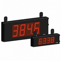
TIMER 6 DIGIT 4.0" 120VAC RED
Manufacturer
Red Lion Controls
Series
LDr
Type
Timerr
Specifications of LD4T06P0
No. Of Digits / Alpha
6
Digit Height
101mm
Power Consumption
26VA
Operating Temperature Range
0°C To +50°C
Signal Input Type
Pulse
Character Size
4"
Ip/nema Rating
IP65 / NEMA 4X
Signal Output Type
Relay
Accuracy
±0.01% %
Connection Type
Wire Leads
Dimensions
26"L×2.25"W×7.875"H
Display Digit Height
4 "
Display Resolution
0.001 Sec. (Minimum Digit), 1 hr. (Single Digit)
Display Type
LED
Function
Timer
Material, Casing
Aluminum
Number Of Digits
6
Primary Type
Electronic
Range, Measurement
0 to 999999
Special Features
RS485/RS232 Communications
Termination
Terminal Block
Voltage, Supply
85 to 250/11 to 16 VAC/VDC
Supply Voltage Range
21.6V DC To 250V DC
Count Speed Max
10Hz
External Depth
57.15mm
External Length / Height
200mm
Rohs Compliant
Yes
Counter Supply Voltage
85-250VAC/11-16VDC
Display Font Color
Red
Lead Free Status / RoHS Status
Lead free / RoHS Compliant
Lead Free Status / RoHS Status
Lead free / RoHS Compliant, Lead free / RoHS Compliant
Other names
RLC125


RS485 Communications
devices on a single pair of wires, distances up to 4,000 ft. and data rates as high
as 10M baud (the LD is limited to 38.4k baud). The same pair of wires is used
to both transmit and receive data. RS485 is therefore always half-duplex, that is,
data cannot be received and transmitted simultaneously.
3.4 INPUT WIRING
inputs are wired using the six position terminal block (TBB) located inside the
unit on the right side.
3.5 SERIAL WIRING
unit on the left side for the LD2 and on the right side for the LD4.
Two Wire Proximity, Current Source
Interfacing With TTL
The RS485 communication standard allows the connection of up to 32
The Large Display Timer is equipped with two signal inputs, A and B. These
The serial connections are made via terminal block TBD located inside the
ON
ON
1 2 3 4
1 2
*
TBB
* *
Switch position is application dependent.
3 4
TBB
*
CAUTION: DC common is NOT isolated from input common. In order to preserve the safety of the meter application, the DC common must be suitably
RESET/USER
RESET/USER
INP COMM
INP COMM
RS485 Terminal Block Connection Figure
isolated from hazardous live earth referenced voltage; or input common must be at protective earth ground potential. If not, hazardous voltage may
be present at the User Input and Input Common terminals. Appropriate considerations must then be given to the potential of the input common with
respect to earth ground.
COMM
COMM
INP A
INP B
+EXC
INP A
INP B
+EXC
1
2
3
4
5
6
5
6
1
2
3
4
2.2 kΩ
5
4
3
Input A
Input A
+5 V
COMMON
Current Sinking Output
Switch or Isolated Transistor; Current Sink
ON
ON
1
1
2
2
* *
3 4
TBB
* *
3 4
TBB
RESET/USER
RESET/USER
INP COMM
INP COMM
COMM
COMM
INP A
INP B
+EXC
INP A
INP B
+EXC
1
2
3
4
5
6
1
2
3
4
5
6
5
RS232 Communications
50 feet. Data Terminal Equipment (DTE) transmits data on the Transmitted Data
(TXD) line and receives data on the Received Data (RXD) line. Data Computer
Equipment (DCE) receives data on the TXD line and transmits data on the RXD
line. The LD emulates a DTE. If the other device connected to the meter also
emulates a DTE, the TXD and RXD lines must be interchanged for
communications to take place. This is known as a null modem connection. Most
printers emulate a DCE device while most computers emulate a DTE device.
without a pause in between. In these cases, the meter employs a busy function.
determine if the receiving device is “busy”. The receiving device asserts that it
is busy by setting the RXD line to a space condition (logic 0). The meter then
suspends transmission until the RXD line is released by the receiving device.
Terminal 1: Input A
Terminal 3: Input B
Terminal 2: Input Common
RS232 is intended to allow two devices to communicate over distances up to
Some devices cannot accept more than two or three characters in succession
As the meter begins to transmit data, the RXD line (RS232) is monitored to
NPN
O.C.
Input A
Input A
RS232 Terminal Block Connection Figure
1
2
3
Current Sourcing Output
Switch or Isolated Transistor; Current Source
ON
ON
1 2 3
1 2 3
*
*
TBB
TBB
*
4
*
4
RESET/USER
RESET/USER
INP COMM
INP COMM
COMM
COMM
INP A
INP B
+EXC
INP A
+EXC
INP B
5
6
1
2
3
4
1
2
3
4
5
6
PNP
O.C.
Input A
Input A
Related parts for LD4T06P0
Image
Part Number
Description
Manufacturer
Datasheet
Request
R

Part Number:
Description:
Counter
Manufacturer:
Red Lion Controls
Datasheet:
Part Number:
Description:
Miniature Length Sensor
Manufacturer:
Red Lion Controls
Datasheet:
Part Number:
Description:
Model Lsc - Single Channel Output Length Sensor
Manufacturer:
Red Lion Controls
Datasheet: