H5CX-A AC100-240 Omron, H5CX-A AC100-240 Datasheet - Page 26
H5CX-A AC100-240
Manufacturer Part Number
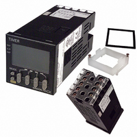
H5CX-A AC100-240
Description
RELAY TIMER DIGITAL SPDT 100/240
Manufacturer
Omron
Series
H5CXr
Specifications of H5CX-A AC100-240
Relay Type
Integrated
Function
Programmable (Multi-Function)
Circuit
SPDT (1 Form C)
Delay Time
0.001 Sec ~ 9999 Hrs
Output Type
Mechanical Relay
Contact Rating @ Voltage
5A @ 250VAC
Voltage - Supply
100 ~ 240VAC
Mounting Type
Panel Mount
Termination Style
Screw Terminal
Timing Adjustment Method
DIP Switches
Timing Initiate Method
Input Voltage, Trigger Signal
Lead Free Status / RoHS Status
Contains lead / RoHS compliant by exemption
Other names
H5CX-A-AC100-240
H5CXAAC100240
Z1645
H5CXAAC100240
Z1645


■ Operating Procedures (Twin Timer Function)
Switching from Timer to Twin Timer
The H5CX is factory-set for timer operation. To switch to twin timer operation, use the procedure given below. For details, refer to page 32.
Settings for Basic Functions
Note: All the pins are factory-set to OFF.
Note 1. Be sure to set pin 1 of the DIP switch to ON. If it is set to OFF, the DIP switch settings will not be enabled.
Timer/
twin timer
selection
1
2
3
4
5
6
7
8
Easy Confirmation of Switch Settings Using Indicators
The ON/OFF status of the DIP switch pins can be confirmed
using the front display. For details, refer to page 31.
Switch from timer operation (
twin timer (
Settings for basic functions can be performed with just the DIP switch.
After making DIP switch settings for basic functions, detailed settings (see note) can be added using the operation keys.
For details, refer to page 27.
Note: NPN/PNP input mode, display color, key protect level.
Detailed Settings
Timer/twin timer selection mode
2. Changes to DIP switch settings are enabled when the power is turned ON. (Perform DIP switch settings while the power is OFF.)
3. There is no DIP switch on the H5CX-L8@. For details on the setting methods, refer to page 27.
4. When using time ranges that cannot be set with the DIP switch, all of the settings have to be made using the operation keys. For details
on the setting methods, refer to page 27.
keys.
DIP switch set-
tings enable/
disable
OFF time range Refer to the table on the right.
ON time range
ON/OFF start
mode
Timer mode
Input signal
width
Item
) operation using the
Disabled
Refer to the table on the right.
Flicker OFF
start
UP
20 ms
) to
+
OFF
1
Hold down for 1 s
min. (See note.)
OFF
ON
Enabled
Flicker ON start
DOWN
1 ms
1
Be sure to set pin 1 to ON when using the DIP switch.
ON
2
3
Power ON
Run mode
4
5
6
7
Note: The
8
before the
OFF
ON
OFF
ON
OFF
ON
OFF
ON
Pin 2
Pin 4
key must be pressed
1
key.
OFF
OFF
ON
ON
Pin 3
OFF
OFF
ON
ON
Pin 5
0.01 s to 99.99 s
0.1 s to 999.9 s
1 s to 9999 s
0 min 01 s to 99 min 59 s
0.01 s to 99.99 s
0.1 s to 999.9 s
1 s to 9999 s
0 min 01 s to 99 min 59 s
OFF time range
ON time range
H5CX-A/-L
26
Related parts for H5CX-A AC100-240
Image
Part Number
Description
Manufacturer
Datasheet
Request
R

Part Number:
Description:
Relay; E-Mech; Timing; Multi-Function; Cur-Rtg 5A; Ctrl-V 100-240AC; REPL:H5CX-AAC1002
Manufacturer:
Omron Automation
Datasheet:
Part Number:
Description:
Digital Timer
Manufacturer:
Omron Corporation
Datasheet:
Part Number:
Description:
Relay; E-Mech; Timing; Multi-Function; Cur-Rtg 5A; Ctrl-V 100-240AC; Socket Mnt; 8 Pin
Manufacturer:
Omron Automation
Datasheet:
Part Number:
Description:
Relay; E-Mech; Timing; Multi-Function; Cur-Rtg 5A; Ctrl-V 100-240AC; Socket Mnt; 11 Pin
Manufacturer:
Omron Automation
Datasheet:
Part Number:
Description:
Relay; E-Mech; Timing; Multi-Function; Cur-Rtg 5A; Ctrl-V 24/12-24AC/DC; Screw; 11 Pin
Manufacturer:
Omron Automation
Datasheet:
Part Number:
Description:
Relay; E-Mech; Timing; Multi-Function; Cur-Rtg 5A; Ctrl-V 24/12-24AC/DC; Socket Mnt
Manufacturer:
Omron Automation
Datasheet:
Part Number:
Description:
Relay; E-Mech; Timing; Multi-Function; Cur-Rtg 5A; Ctrl-V 24/12-24AC/DC; Socket Mnt
Manufacturer:
Omron Automation
Datasheet:
Part Number:
Description:
G6S-2GLow Signal Relay
Manufacturer:
Omron Corporation
Datasheet:
Part Number:
Description:
Compact, Low-cost, SSR Switching 5 to 20 A
Manufacturer:
Omron Corporation
Datasheet:
Part Number:
Description:
Manufacturer:
Omron Corporation
Datasheet:
Part Number:
Description:
Manufacturer:
Omron Corporation
Datasheet: