GA355QR7GF332KW01L Murata Electronics North America, GA355QR7GF332KW01L Datasheet - Page 151
GA355QR7GF332KW01L
Manufacturer Part Number
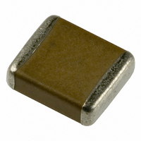
GA355QR7GF332KW01L
Description
CAP CER 250VAC 3300PF X7R 2220
Manufacturer
Murata Electronics North America
Series
GFr
Datasheets
1.GNM1M2R71E472MA01D.pdf
(4 pages)
2.GA342QR7GD471KW01L.pdf
(221 pages)
3.GA355QR7GF332KW01L.pdf
(1 pages)
Specifications of GA355QR7GF332KW01L
Capacitance
3300pF
Voltage - Rated
250VAC
Tolerance
±10%
Temperature Coefficient
X7R
Mounting Type
Surface Mount, MLCC
Operating Temperature
-55°C ~ 125°C
Features
High Voltage
Applications
Safety
Ratings
X1Y2
Package / Case
2220 (5750 Metric)
Size / Dimension
0.224" L x 0.197" W (5.70mm x 5.00mm)
Thickness
1.50mm
Lead Free Status / RoHS Status
Lead free / RoHS Compliant
Lead Spacing
-
Other names
490-3481-2
Available stocks
Company
Part Number
Manufacturer
Quantity
Price
Company:

Part Number:
GA355QR7GF332KW01L
Manufacturer:
MURATA
Quantity:
640 000
Company:
Part Number:
GA355QR7GF332KW01L
Manufacturer:
MURATA
Quantity:
200
Part Number:
GA355QR7GF332KW01L
Manufacturer:
MURATA/村田
Quantity:
20 000


!Note
• This PDF catalog is downloaded from the website of Murata Manufacturing co., ltd. Therefore, it’s specifications are subject to change or our products in it may be discontinued without advance notice. Please check with our
• This PDF catalog has only typical specifications because there is no space for detailed specifications. Therefore, please approve our product specifications or transact the approval sheet for product specifications before ordering.
sales representatives or product engineers before ordering.
!Note
7. Coating
1. A crack may be caused in the capacitor due to the stress
8. Die Bonding/Wire Bonding (GMA or GMD Series)
1. Die Bonding of Capacitors
Notice
of the thermal contraction of the resin during curing
process.
The stress is affected by the amount of resin and curing
contraction.
Select a resin with small curing contraction.
The difference in the thermal expansion coefficient
between a coating resin or a molding resin and the
capacitor may cause the destruction and deterioration of
the capacitor such as a crack or peeling, and lead to the
deterioration of insulation resistance or dielectric
breakdown.
• Use the following materials for the Brazing alloys:
• Mounting
Continued from the preceding page.
Au-Sn (80/20) 300 to 320 C in N
(1) Control the temperature of the substrate so it
(2) Place the brazing alloy on the substrate and place
• Please read rating and !CAUTION (for storage, operating, rating, soldering, mounting and handling) in this catalog to prevent smoking and/or burning, etc.
• This catalog has only typical specifications because there is no space for detailed specifications. Therefore, please approve our product specifications or transact the approval sheet for product specifications before ordering.
matches the temperature of the brazing alloy.
the capacitor on the alloy. Hold the capacitor and
gently apply the load. Be sure to complete the
operation within 1 minute.
2
atmosphere
2. Select a resin that is less hygroscopic.
2. Wire Bonding
Select a resin for which the thermal expansion coefficient
is as close to that of capacitor as possible.
A silicone resin can be used as an under-coating to buffer
against the stress.
Using hygroscopic resins under high humidity conditions
may cause the deterioration of the insulation resistance of
a capacitor.
An epoxy resin can be used as a less hygroscopic resin.
• Wire
• Bonding
Gold wire: 25 micro m (0.001 inch) diameter
(1) Thermo compression, ultrasonic ball bonding.
(2) Required stage temperature: 150 to 200 C
(3) Required wedge or capillary weight: 0.2N to 0.5N
(4) Bond the capacitor and base substrate or other
devices with gold wire.
Notice
149
C02E.pdf
10.12.20
Related parts for GA355QR7GF332KW01L
Image
Part Number
Description
Manufacturer
Datasheet
Request
R

Part Number:
Description:
BUZZER PIEZO 25VP-P SMD
Manufacturer:
Murata Electronics North America

Part Number:
Description:
CAP 4-ARRAY 680PF 100V X7R 1206
Manufacturer:
Murata Electronics North America
Datasheet:
Part Number:
Description:
CAP 4-ARRAY 1000PF 100V X7R 1206
Manufacturer:
Murata Electronics North America
Datasheet:
Part Number:
Description:
CAP 4-ARRAY 1800PF 100V X7R 1206
Manufacturer:
Murata Electronics North America
Datasheet:
Part Number:
Description:
CAP 4-ARRAY 68000PF 16V X7R 1206
Manufacturer:
Murata Electronics North America
Datasheet:

Part Number:
Description:
CAP CER 1000PF 50V 10% X7R 0402
Manufacturer:
Murata Electronics North America
Datasheet:
Part Number:
Description:
CAP CER 10000PF 16V 10% X7R 0402
Manufacturer:
Murata Electronics North America
Datasheet:

Part Number:
Description:
CAP 5.5-25PF 2.5X3.2MM SMD
Manufacturer:
Murata Electronics North America
Datasheet:

Part Number:
Description:
CAP 4.5-20PF 2.5X3.2MM SMD
Manufacturer:
Murata Electronics North America
Datasheet:

Part Number:
Description:
CAP 5.0-20PF 3.2X4.5MM SMD RED
Manufacturer:
Murata Electronics North America
Datasheet:

Part Number:
Description:
CAP 2.0-6.0PF 3.2X4.5MM SMD BLU
Manufacturer:
Murata Electronics North America
Datasheet:

Part Number:
Description:
CAP 1.4-3.0PF 3.2X4.5MM SMD BRN
Manufacturer:
Murata Electronics North America
Datasheet:

Part Number:
Description:
CAP 3.0-10PF 3.2X4.5MM SMD WHT
Manufacturer:
Murata Electronics North America
Datasheet:

Part Number:
Description:
CAP 2.0-6.0PF 4X4.5MM TOPADJ BLU
Manufacturer:
Murata Electronics North America
Datasheet:

Part Number:
Description:
CAP 8.5-40PF 4X4.5MM TOPADJ YEL
Manufacturer:
Murata Electronics North America
Datasheet: