LM3409HVMY/NOPB National Semiconductor, LM3409HVMY/NOPB Datasheet
LM3409HVMY/NOPB
Specifications of LM3409HVMY/NOPB
Available stocks


Related parts for LM3409HVMY/NOPB


LM3409HVMY/NOPB Summary of contents
Page 1
... PWM dimming are easy to implement and result in a highly linear dimming range with excellent achievable contrast ra- tios. Programmable UVLO, low-power shutdown, and thermal shutdown complete the feature set. Typical Application © 2011 National Semiconductor Corporation LM3409 / LM3409HV LM3409Q / LM3409QHV Features ■ ...
Page 2
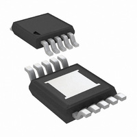
Connection Diagram Ordering Information Order Number NSC Package Drawing LM3409MY MUC10A LM3409MYX MUC10A LM3409HVMY MUC10A LM3409HVMYX MUC10A LM3409QMY MUC10A LM3409QMYX MUC10A LM3409QHVMY MUC10A LM3409QHVMYX MUC10A *Automotive Grade (Q) product incorporates enhanced manufacturing and support processes for the automotive market, including ...
Page 3
... Absolute Maximum Ratings LM3409/09Q/09HV/09QHV If Military/Aerospace specified devices are required, please contact the National Semiconductor Sales Office/ Distributors for availability and specifications. VIN, EN, UVLO to GND VIN to VCC, PGATE VIN to PGATE VIN to CSP, CSN COFF to GND COFF current IADJ Current Junction Temperature Storage Temp. Range ...
Page 4
Symbol Parameter OFF-TIMER AND ON-TIMER V Off-time threshold OFT t COFF threshold to PGATE D-OFF falling delay t Minimum on-time ON-MIN t Maximum off-time OFF-MAX UNDER VOLTAGE LOCKOUT I UVLO pin current UVLO V Rising UVLO threshold UVLO-R I UVLO ...
Page 5
Typical Performance Characteristics T = +25° 24V, and characteristics are identical for LM3409 and LM3409HV unless otherwise specified vs. Junction Temperature CST V vs. Junction Temperature ADJ V vs. Junction Temperature OFT V vs. Junction ...
Page 6
LM3409 Efficiency vs. Input Voltage V = 17V (5 LEDs LED LM3409 LED Current vs. Input Voltage V = 17V (5 LEDs) O Normalized Switching Frequency vs. Input Voltage www.national.com LM3409HV Efficiency vs. Input Voltage (Note 8) = ...
Page 7
Internal EN Pin PWM Dimming V = 17V (5 LEDs 24V O IN 20kHz 50% EN pin PWM dimming (Note V = 42V (12 LEDs 48V O IN 20kHz 50% EN pin PWM dimming (rising edge) ...
Page 8
Block Diagram Theory of Operation The LM3409/09HV are P-channel MosFET (PFET) con- trollers for step-down (buck) current regulators which are ideal for driving LED loads. They have wide input voltage range allowing for regulation of a variety of LED loads. ...
Page 9
FIGURE 1. Ideal CCM Buck Converter Inductor Current i CONTROLLED OFF-TIME (COFT) ARCHITECTURE The COFT architecture is used by the LM3409/09HV to con- trol combination of peak current detection and a LED one-shot off-timer that ...
Page 10
There are three different methods to set the current sense threshold (V ) using the multi-function IADJ pin: CST 1. IADJ pin left open: 5µA internal current source biases the Zener diode and clamps the IADJ pin voltage (V 1.24V ...
Page 11
AVERAGE LED CURRENT For a buck converter, the average LED current is simply the average inductor current. FIGURE 5. Sense Voltage v Using the COFT architecture, the peak transistor current ( sensed as shown in Figure 5, which ...
Page 12
FIGURE 7. LED Current i PWM DIMMING USING THE EN PIN The enable pin (EN TTL compatible input for PWM dim- ming of the LED. A logic low (below 0.5V will disable the internal driver and ...
Page 13
Design Considerations OPERATION NEAR DROPOUT Because the power MosFET is a PFET, the LM3409/09HV can be operated into dropout which occurs when the input voltage is approximately equal to output voltage. Once the input voltage drops below the nominal output ...
Page 14
INPUT CAPACITORS Input capacitors are selected using requirements for mini- mum capacitance and RMS ripple current. The PFET current during t is approximately I , therefore the input capacitors ON LED discharge the difference between I LED current (I ) ...
Page 15
FIGURE 10. Ideal LED Current i EXTERNAL PARALLEL FET PWM DIMMING Any buck topology LED driver is a good candidate for parallel FET dimming because high slew rates are achievable, due to the fact that no output capacitance is required. ...
Page 16
Design Guide TYPICAL APPLICATION SPECIFICATIONS Nominal input voltage Maximum input voltage: V IN-MAX Nominal output voltage (# of LEDs x forward voltage): V LED string dynamic resistance Switching frequency (at nominal V IN Average LED current: ...
Page 17
OUTPUT CAPACITANCE A minimum output capacitance (C ) may be necessary to O-MIN reduce Δi below Δi . With the specified Δi LED-PP L-PP the known dynamic resistance ( the LED string, solve for D the required ...
Page 18
Design Example #1 EN PIN PWM DIMMING APPLICATION FOR 10 LEDS SPECIFICATIONS f = 525kHz 48V 75V IN IN-MAX V = 35V LED Δi = Δ LED-PP L-PP Δv ...
Page 19
AVERAGE LED CURRENT Determine I : L-MAX Assume V = 1.24V and solve for R ADJ SNS The closest 1% tolerance resistor is 0.1 Ω therefore the I is: The chosen component from step 3 is: 4. OUTPUT CAPACITANCE ...
Page 20
INPUT UVLO Solve for R : UV2 The closest 1% tolerance resistor is 49.9 kΩ therefore V is: Solve for R : UV1 Design #1 Bill of Materials Qty Part ID 1 LM3409HV/ LM3409QHV IN1 ...
Page 21
Design Example #2 ANALOG DIMMING APPLICATION FOR 4 LEDS SPECIFICATIONS f = 500kHz 24V 42V IN IN-MAX V = 14V LED Δi = 450mA; Δi = 50mA L-PP LED-PP Δv = ...
Page 22
AVERAGE LED CURRENT Determine I : L-MAX Assume V = 1.24V and solve for R ADJ The closest 1% tolerance resistor is 0.2 Ω therefore I The chosen component from step 3 is: 4. OUTPUT CAPACITANCE = 2 Ω ...
Page 23
INPUT UVLO Solve for R : UV2 The closest 1% tolerance resistor is 49.9 kΩ therefore V is: Solve for R : UV1 Design #2 Bill of Materials Qty Part ID 1 LM3409/LM3409Q 2 C IN1 ...
Page 24
Applications Information DESIGN #3: EXTERNAL PARALLEL FET PWM DIMMING APPLICATION FOR 10 LEDS Design #3 Bill of Materials Qty Part ID 1 LM3409HV/ LM3409QHV IN1 IN2 OFF ...
Page 25
DESIGN #4: SINGLE POTENTIOMETER ANALOG DIMMING APPLICATION FOR 6 LEDS Design #4 Bill of Materials Qty Part ID 1 LM3409/LM3409Q IN1 IN2 OFF ...
Page 26
DESIGN #5: 75°C THERMAL FOLDBACK APPLICATION FOR 16 LEDS Design #5 Bill of Materials Qty Part ID 1 LM3409HV/ LM3409QHV IN1 IN2 OFF ...
Page 27
DESIGN #6: HIGH CURRENT APPLICATION FOR 4 LEDS Design #6 Bill of Materials Qty Part ID 1 LM3409/LM3409Q 2 C 10µF X7R 10% 50V IN1 1 C 1.0µF X7R 10% 16V 0.1µF X7R 10% 16V F2 1 ...
Page 28
Physical Dimensions www.national.com inches (millimeters) unless otherwise noted 10-Lead Exposed Pad Plastic eMSOP Package NS Package Number MUC10A 28 ...
Page 29
Notes 29 www.national.com ...
Page 30
... For more National Semiconductor product information and proven design tools, visit the following Web sites at: www.national.com Products Amplifiers www.national.com/amplifiers Audio www.national.com/audio Clock and Timing www.national.com/timing Data Converters www.national.com/adc Interface www.national.com/interface LVDS www.national.com/lvds Power Management www.national.com/power Switching Regulators www.national.com/switchers LDOs www.national.com/ldo LED Lighting www ...