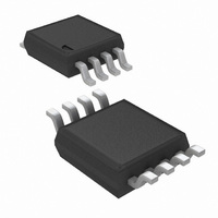
LMV852MM/NOPB National Semiconductor, LMV852MM/NOPB Datasheet

LMV852MM/NOPB
Specifications of LMV852MM/NOPB
Available stocks
Related parts for LMV852MM/NOPB
LMV852MM/NOPB Summary of contents
Page 1
... Over an operating supply range from 2.7V to 5.5V the LMV851/LMV852/LMV854 provide a CMRR of 92 dB, and a PSRR of 93 dB. The LMV851/LMV852/LMV854 are offered in the space saving 5-Pin SC70 package, the 8-Pin MSOP and the 14-Pin TSSOP package. Typical Application © 2007 National Semiconductor Corporation Features Unless otherwise noted, typical values 3.3V SUPPLY ■ ...
Page 2
... Absolute Maximum Ratings If Military/Aerospace specified devices are required, please contact the National Semiconductor Sales Office/ Distributors for availability and specifications. ESD Tolerance (Note 2) Human Body Model Charge-Device Model Machine Model V Differential IN Supply Voltage (V + – V − ) Voltage at Input/Output Pins 3.3V Electrical Characteristics Unless otherwise specified, all limits are guaranteed for T Boldface limits apply at the temperature extremes ...
Page 3
Symbol Parameter I Output Short Circuit Current O I Supply Current S SR Slew Rate (Note 7) GBW Gain Bandwidth Product Φ Phase Margin m e Input-Referred Voltage Noise n i Input-Referred Current Noise n R Closed Loop Output Impedance ...
Page 4
Symbol Parameter A Large Signal Voltage Gain VOL (Note 11) V Output Swing High, O (measured from Output Swing Low, (measured from V − Output Short Circuit Current O I Supply Current S SR Slew ...
Page 5
Connection Diagrams 5-Pin SC70 20202102 Top View Ordering Information Package Part Number LMV851MG 5-Pin SC70 LMV851MGX LMV852MM 8-Pin MSOP LMV852MMX LMV854MT 14-Pin TSSOP LMV854MTX 8-Pin MSOP 20202103 Top View Package Marking Transport Media 1k Units Tape and Reel A98 3k ...
Page 6
Typical Performance Characteristics vs. Supply Voltage www.national.com 25° 20202110 20202112 OUT 20202114 kΩ 3.3V, unless otherwise specified. ...
Page 7
Input Bias Current vs 85°C CM Supply Current vs. Supply Voltage Single LMV851 Supply Current vs. Supply Voltage Quad LMV854 Input Bias Current vs. V 20202116 Supply Current vs. Supply Voltage Dual LMV852 20202118 Supply Current vs. Temperature ...
Page 8
Supply Current vs. Temperature Dual LMV852 Sinking Current vs. Supply Voltage Output Swing High vs. Supply Voltage R www.national.com Supply Current vs. Temperature Quad LMV854 20202122 Sourcing Current vs. Supply Voltage 20202124 = 2 kΩ Output Swing High vs. Supply ...
Page 9
Output Swing Low vs. Supply Voltage R Output Voltage Swing vs. Load Current at 3.3V Open Loop Frequency Response vs. Temperature = 2 kΩ Output Swing Low vs. Supply Voltage R L 20202128 Output Voltage Swing vs. Load Current at ...
Page 10
Phase Margin vs. Capacitive Load CMRR vs. Frequency Large Signal Step Response with Gain = 1 www.national.com PSRR vs. Frequency 20202133 Channel Separation vs. Frequency 20202136 Large Signal Step Response with Gain = 10 20202138 10 20202135 20202137 20202139 ...
Page 11
Small Signal Step Response with Gain = 1 20202140 Slew Rate vs. Supply Voltage Input Voltage Noise vs. Frequency Small Signal Step Response with Gain = 10 Overshoot vs. Capacitive Load 20202142 THD+N vs. Frequency 20202144 11 20202141 20202143 20202145 ...
Page 12
THD+N vs. Amplitude EMIRR IN + vs. Power at 400 MHz EMIRR IN + vs. Power at 1800 MHz www.national.com R vs. Frequency OUT 20202146 EMIRR IN + vs. Power at 900 MHz 20202149 EMIRR IN + vs. Power at ...
Page 13
EMIRR IN + vs. Frequency at 3.3V EMIRR IN + vs. Frequency at 5.0V 20202153 13 20202154 www.national.com ...
Page 14
Application Information INTRODUCTION The LMV851/LMV852/LMV854 are operational amplifiers with very good specifications, such as low offset, low noise and a rail-to-rail output. These specifications make the LMV851/LMV852/LMV854 great choices to use in areas such as medical and instrumentation. The low ...
Page 15
OUTPUT CHARACTERISTICS As already mentioned the output is rail to rail. When loading the output with a 10 kΩ resistor the maximum swing of the output is typically 7 mV from the positive and negative rail The LMV851/LMV852/LMV854 can be ...
Page 16
FIGURE 5. Circuit for Coupling the RF Signal to IN Cell Phone Call The effect of electromagnetic interference is demonstrated in a setup where a cell phone interferes with a ...
Page 17
THERMOCOUPLE AMPLIFIER The following circuit is a typical example for a thermocouple amplifier application using an LMV851/LMV852, or LMV854. A thermocouple converts a temperature into a voltage. This signal is then amplified by the LMV851/LMV852, or LMV854. An ADC can ...
Page 18
Unwanted Thermocouple Effect At the point where the thermocouple wires are connected to the circuit, usually copper wires or traces, an unwanted ther- mocouple effect will occur. At this connection, this could be the connector on a PCB, the thermocouple ...
Page 19
Physical Dimensions inches (millimeters) unless otherwise noted 5-Pin SC70 NS Package Number MAA05A 8-Pin MSOP NS Package Number MUA08A 19 www.national.com ...
Page 20
TSSOP NS Package Number MTC14 20 ...
Page 21
Notes 21 www.national.com ...
Page 22
... National Semiconductor and the National Semiconductor logo are registered trademarks of National Semiconductor Corporation. All other brand or product names may be trademarks or registered trademarks of their respective holders. ...


