ESDA8V2-1MX2 STMicroelectronics, ESDA8V2-1MX2 Datasheet
ESDA8V2-1MX2
Specifications of ESDA8V2-1MX2
ESDA8V2-1MX2
Available stocks


Related parts for ESDA8V2-1MX2


ESDA8V2-1MX2 Summary of contents
Page 1
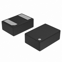
... Cellular phone handsets and accessories ■ Video equipment August 2008 2 ) Figure 1. Description The ESDA8V2-1MX2 is a unidirectional single line Transil diode designed specifically for the protection of integrated circuits in portable equipment and miniaturized electonic devices subject to EOS and ESD transient overvoltages. TM: Transil is a trademark of STMicroelectronics Rev 1 ESDA8V2-1MX2 µ ...
Page 2
... (8/20 µs waveform (8/20 µs waveform (8/20 µs waveform line R osc 2/ °C) amb Parameter ( initial °C) amb MHz osc ESDA8V2-1MX2 Value ±30 ±30 ± 500 amb 27 -40 to +125 - 55 to +150 260 Slope Min Typ Max 8.2 0.1 0 18.5 350 430 Unit ...
Page 3
... ESDA8V2-1MX2 Figure 2. Relative variation of peak pulse power versus initial junction temperature (8/20 µs, typical values) Figure 4. Clamping voltage versus peak pulse current (8/20 µs, typical values) Figure 6. Junction capacitance versus reverse voltage applied (typical values) Figure 3. Peak pulse power versus exponential pulse duration (typical values) Figure 5 ...
Page 4
... Ordering information scheme Figure 7. ESD response to IEC 61000-4-2 (+30 kV air discharge) 2 Ordering information scheme Figure 9. Ordering information scheme 4/10 Figure 8. ESD response to IEC 61000-4-2 (-30 kV air discharge) ESDA8V2-1MX2 ...
Page 5
... ESDA8V2-1MX2 3 Package information ● Epoxy meets UL94 order to meet environmental requirements, ST offers these devices in ECOPACK packages. These packages have a lead-free second level interconnect. The category of second level interconnect is marked on the inner box label, in compliance with JEDEC Standard JESD97. The maximum ratings related to soldering conditions are also marked on the inner box label ...
Page 6
... Package information Figure 12. Tape and reel specifications 6/10 ESDA8V2-1MX2 ...
Page 7
... ESDA8V2-1MX2 4 Recommendation on PCB assembly 4.1 Stencil opening design 1. General recommendation on stencil opening design a) Stencil opening dimensions: L (Length), W (Width), T (Thickness). Figure 13. Stencil opening dimensions b) General design rule Stencil thickness ( 125 µm Aspect Ratio Aspect Area 2. Reference design a) Stencil opening thickness: 100 µm b) Stencil opening for leads: Opening to footprint ratio - between 40% and 50% ...
Page 8
... To control the solder paste amount, the closed via is recommended instead of open vias. 2. The position of tracks and open vias in the solder area should be well balanced. The symmetrical layout is recommended, in case any tilt phenomena caused by asymmetrical solder paste amount due to the solder flow away. 8/10 ESDA8V2-1MX2 ...
Page 9
... Note: Minimize air convection currents in the reflow oven to avoid component movement. 5 Ordering information Table 5. Ordering information Order code ESDA8V2-1MX2 1. The marking can be rotated by 90° to diferentiate assembly location 6 Revision history Table 6. Document revision history Date 27-Aug-2008 3°C/s max 3°C/s max ...
Page 10
... Australia - Belgium - Brazil - Canada - China - Czech Republic - Finland - France - Germany - Hong Kong - India - Israel - Italy - Japan - Malaysia - Malta - Morocco - Singapore - Spain - Sweden - Switzerland - United Kingdom - United States of America 10/10 Please Read Carefully: © 2008 STMicroelectronics - All rights reserved STMicroelectronics group of companies www.st.com ESDA8V2-1MX2 ...