T491B155K025AS Kemet, T491B155K025AS Datasheet - Page 12
T491B155K025AS
Manufacturer Part Number
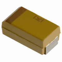
T491B155K025AS
Description
CAPACITOR TANT 1.5UF 25V 10% SMD
Manufacturer
Kemet
Series
T491r
Type
Moldedr
Datasheet
1.T491B155K025AS.pdf
(100 pages)
Specifications of T491B155K025AS
Capacitance
1.5µF
Voltage - Rated
25V
Tolerance
±10%
Esr (equivalent Series Resistance)
5.000 Ohm
Operating Temperature
-55°C ~ 125°C
Mounting Type
Surface Mount
Package / Case
1210 (3528 Metric)
Size / Dimension
0.138" L x 0.110" W (3.50mm x 2.80mm)
Height
0.075" (1.90mm)
Manufacturer Size Code
B
Features
General Purpose
Lead Free Status / RoHS Status
Contains lead / RoHS non-compliant
Lead Spacing
-
Other names
399-1625-2


10
Product subjected to above test condition
demonstrate no sensitivity to electrostatic
discharge.
Mounted capacitors withstand extreme temperature
testing at a succession of continuous steps at
+25°C, -55°C, +25°C, +85°C, +125°C, +25°C, in the
order stated. Capacitors shall be brought to thermal
stability at each test temperature. Capacitance, DF
and DCL are measured at each test temperature
except that DCL is not measured at -55°C. DC bias
of 2.0± 0.5 is recommended for the capacitance
and D F requirements.
Minimum temperature -55°C, mounted
Post Test Performance:
Steps 7a and 7b excluded, rated voltage,
42 cycles, mounted
Post Test Performance:
Within the general class of electrolytic capacitors,
solid tantalum capacitors offer unusual stability of
the three important parameters: capacitance, dis-
sipation factor and leakage current. These solid-
state devices are not subject to the effects of
electrolysis, deforming or drying-out associated
with liquid-electrolyte capacitors.
When stabilized for measurement at standard
conditions, capacitance will typically change less
than ±3% during a 10,000 hour life test +85°C.
a. Capacitance — within ±5% of initial value
b. DC Leakage — within initial limit
c. Dissipation Factor — within initial limit
d. ESR — within initial limit
a. Capacitance — within ±10% of initial value
b. DC Leakage — within initial limit
c. Dissipation Factor — within initial limit
d. ESR — within initial limit
Mil-Std-202, Method 107, Condition B
Mil-Std-202, Method 106
JEDEC J-STD-20C — meets MSL1 for Pb-free
assembly
Human Body Model
2,000 ±50 volts, 1,500 ±5% ohms, 40 nano-
second pulse each polarity, 1 pulse each
polarity, 5 seconds between pulses, +25 C.
Charged Device Model
200 ± 5 volts, 0 ohms, 40 nanosecond
pulse, each polarity, 9 pulses each polarity,
5 seconds between pulses, +25 C.
©KEMET Electronics Corporation, P.O. Box 5928, Greenville, S.C. 29606, (864) 963-6300
SOLID TANTALUM CHIP CAPACITORS
The same comparative change has been
observed in shelf tests at +25°C extending for
50,000 hours. (Some of this change may stem
from instrument or fixture error.)
Dissipation factor exhibits no typical trend. Data
from 10,000 hour life test at +85°C show that ini-
tial limits (at standard conditions) are not exceeded
at the conclusion of these tests.
Leakage current is more variable than capaci-
tance or DF; in fact, leakage current typically
exhibits a logarithmic dependence in several
respects. Military Specifications permit leakage
current (measured at standard conditions) to rise
by a factor of four over 10,000 hour life tests.
Typical behavior shows a lower rate of change,
which may be negative or positive. Initial leakage
currents are frequently so low (less than 0.1
nanoampere in the smallest CV capacitors) that
changes of several orders of magnitude have no
discernable effect on the usual circuit designs.
Capacitor failure may be induced by exceeding
50% of rated voltage of the capacitor with forward
DC voltage, reverse DC voltage, power dissipation,
or temperature. As with any practical device, these
capacitors also possess an inherent, although low,
failure rate when operated at less than 50% of the
rated voltage of the capacitor.
The dominant failure mode is by short-circuit.
Minor parametric drifts are of no consequence in
circuits suitable for solid tantalum capacitors.
Catastrophic failure occurs as an avalanche in DC
leakage current over a short (millisecond) time
span. The failed capacitor, while called “short-cir-
cuited”, may exhibit a DC resistance of 10 to 10
ohm.
If a failed capacitor is in an unprotected low-
impedance circuit, continued flow of current
through the capacitor may obviously produce
severe overheating. The over-heated capacitor
may damage the circuit board or nearby compo-
nents. Protection against such occurrence is
obtained by current-limiting devices or fuses pro-
vided by the circuit design. KEMET’s T496 series
offers a built-in fuse to convert the normal short
circuit failure mode to an open circuit.
Fortunately, the inherent failure rate of KEMET
solid tantalum capacitors is low, and this failure
rate may be further improved by circuit design.
Statistical failure rates are provided for military
capacitors. Relating circuit conditions to failure
rate is aided by the guides in the section following.
4
Related parts for T491B155K025AS
Image
Part Number
Description
Manufacturer
Datasheet
Request
R

Part Number:
Description:
CAP, KEMET #F601BL105K250C
Manufacturer:
Kemet
Datasheet:
Part Number:
Description:
Manufacturer:
Kemet
Datasheet:
Part Number:
Description:
Manufacturer:
Kemet
Datasheet: