T491B155K025AS Kemet, T491B155K025AS Datasheet - Page 15
T491B155K025AS
Manufacturer Part Number
T491B155K025AS
Description
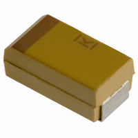
CAPACITOR TANT 1.5UF 25V 10% SMD
Manufacturer
Kemet
Series
T491r
Type
Moldedr
Datasheet
1.T491B155K025AS.pdf
(100 pages)
Specifications of T491B155K025AS
Capacitance
1.5µF
Voltage - Rated
25V
Tolerance
±10%
Esr (equivalent Series Resistance)
5.000 Ohm
Operating Temperature
-55°C ~ 125°C
Mounting Type
Surface Mount
Package / Case
1210 (3528 Metric)
Size / Dimension
0.138" L x 0.110" W (3.50mm x 2.80mm)
Height
0.075" (1.90mm)
Manufacturer Size Code
B
Features
General Purpose
Lead Free Status / RoHS Status
Contains lead / RoHS non-compliant
Lead Spacing
-
Other names
399-1625-2


Post Test Performance:
KEMET
a. Capacitance — within ±5% of initial value
b. DC Leakage — within initial limit
c. Dissipation Factor — within initial limit
Automatic handling of encapsulated components
is enhanced by the molded case which provides
compatibility with all types of high speed pick and
place equipment. Manual handling of these
devices presents no unique problems. Care
should be taken with your fingers, however, to
avoid touching the solder-coated terminations as
body oils, acids and salts will degrade the sol-
derability of these terminations. Finger cots
should be used whenever manually handling all
solderable surfaces.
KEMET's standard termination finish is 100% Sn
(Excluding the T492/3 series. Refer to specific
lead frame options available on T493 Series).
Standard terminations can be ordered with a "T"
suffix in the lead material designator of the
KEMET part number. Components ordered with
the "T" suffix are Pb-Free/RoHS compliant and
are backward and forward compatible with SnPb
R
U
B
C
D
S
T
V
A
X
E
Case Code
©KEMET Electronics Corporation, P.O. Box 5928, Greenville, S.C. 29606, (864) 963-6300
Four Pounds (1.8 kilograms), 60 Seconds
2012-12
3216-12
3528-12
6032-15
7343-20
3216-18
3528-21
6032-28
7343-31
7343-43
7260-38
EIA
4 lb. (1.8 Kg)
SOLID TANTALUM CHIP CAPACITORS
Kilograms
Maximum Shear Loads
2.4
3.2
3.6
4.5
5.0
3.2
3.6
4.5
5.0
5.0
5.0
Pounds
10.0
11.0
10.0
11.0
11.0
11.0
5.3
7.0
8.0
7.0
8.0
R/2012-12
A/3216-18, S/3216-12
B/3528-21, T/3528-12
C/6032-28, U/6032-15
D/7343-31, V/7343-20, X/7343-43
E/7260-38
R/2012-12
A/3216-18, S/3216-12
B/3528-21, T/3528-12
C/6032-28, U/6032-15
D/7343-31, V/7343-20, X/7343-43
E/7260-38
and Pb-Free soldering processes.
90Sn/10Pb terminations are also available and
can be ordered with an "H" suffix.
KEMET's "S" suffix remains an active termination
designator for current designs but is not recom-
mended for new designs. Parts ordered with an
"S" suffix are not guaranteed to be Pb-Free or
RoHS compliant. Refer to www.kemet.com for
information on Pb-Free transition.
For conductive adhesive attachment processes, a
gold termination finish is available for most series and
case sizes. Refer to the specific series for details.
Proper mounting pad geometries are essential
for successful solder connections. These dimen-
sions are highly process sensitive and should be
designed to maximize the integrity of the solder
joint, and to minimize component rework due to
unacceptable solder joints.
Figure 12 illustrates pad geometry. Tables 9 &
10 provide recommended pad dimensions for
both wave and reflow soldering techniques.
These dimensions are intended to be a starting
point
be fine tuned, if necessary, based upon the pecu-
liarities of the soldering process and/or circuit
board design.
Contact KEMET for Engineering Bulletin Number
F-2100 entitled “Surface Mount Mounting Pad
Dimensions and Considerations” for further
details on this subject.
for
circuit
board
3.90
4.70
5.00
7.60
8.90
8.90
4.30
5.10
5.40
8.00
9.70
9.70
0.80
0.80
1.10
2.50
3.80
3.80
0.80
0.80
1.10
2.50
3.80
3.80
designers,
1.80
1.50
2.50
2.50
2.70
4.40
1.26
1.10
1.80
1.80
2.70
4.40
1.55
1.95
1.95
2.55
2.55
2.55
1.75
2.15
2.15
2.75
2.95
2.95
2.35
2.75
3.05
5.05
6.35
6.35
2.55
2.95
3.25
5.25
6.75
6.75
13
to
Related parts for T491B155K025AS
Image
Part Number
Description
Manufacturer
Datasheet
Request
R

Part Number:
Description:
CAP, KEMET #F601BL105K250C
Manufacturer:
Kemet
Datasheet:
Part Number:
Description:
Manufacturer:
Kemet
Datasheet:
Part Number:
Description:
Manufacturer:
Kemet
Datasheet: