T491B155K025AS Kemet, T491B155K025AS Datasheet - Page 71
T491B155K025AS
Manufacturer Part Number
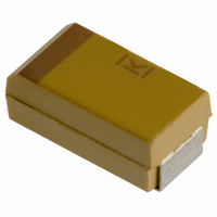
T491B155K025AS
Description
CAPACITOR TANT 1.5UF 25V 10% SMD
Manufacturer
Kemet
Series
T491r
Type
Moldedr
Datasheet
1.T491B155K025AS.pdf
(100 pages)
Specifications of T491B155K025AS
Capacitance
1.5µF
Voltage - Rated
25V
Tolerance
±10%
Esr (equivalent Series Resistance)
5.000 Ohm
Operating Temperature
-55°C ~ 125°C
Mounting Type
Surface Mount
Package / Case
1210 (3528 Metric)
Size / Dimension
0.138" L x 0.110" W (3.50mm x 2.80mm)
Height
0.075" (1.90mm)
Manufacturer Size Code
B
Features
General Purpose
Lead Free Status / RoHS Status
Contains lead / RoHS non-compliant
Lead Spacing
-
Other names
399-1625-2


from that value. For example, a typical IR specification
might read “1,000 megohm-microfarads or 100
gigohms, whichever is less”. The DC leakage current
may be calculated by dividing the applied voltage by
the insulation resistance (Ohm's Law).
voltage which a capacitor is designed to withstand
without damage for short periods of time. All KEMET
multilayer ceramic surface mount capacitors will with-
stand a DC test voltage of 2.5 x the rated voltage for 60
seconds.
istics at standard measurement conditions are shown in
Table 3. Variations in these properties caused by
changing conditions (temperature, voltage, frequency,
and time) are covered in the following sections.
with time as well as with temperature, voltage and fre-
quency. The change with time is known as “aging”. It is
caused by gradual realignment of the crystalline struc-
ture of the ceramic dielectric material as it is cooled
below its Curie temperature, which produces a loss of
capacitance with time. The aging process is predictable
and follows a logarithmic decay.
heated to a temperature above its Curie point for some
period of time, de-aging will occur and the capacitor will
regain the capacitance lost during the aging process.
The amount of de-aging depends on both the elevated
temperature and the length of time at that temperature.
Exposure to 150°C for one-half hour is sufficient to
return the capacitor to its initial value.
ately after de-aging, capacitance measurements are
indexed to a referee time of 1,000 hours. All Kemet
capacitors are shipped to be within tolerance at the
referee time of 1,000 hours after the deaging process
(this time is often referred to as "last heat"). The selection
of this referree time has proven practical, as the actual
decline of capacitance after 1,000 hours is very low.
by variations in temperature. The maximum capacitance
change with temperature is defined by the temperature
characteristic.
Dielectric withstanding voltage (DWV) is the peak DC
KEMET specification limits for all electrical character-
The capacitance of Class II and III dielectric changes
The aging process is reversible. If the capacitor is
Because the capacitance changes rapidly immedi-
Both capacitance and dissipation factor are affected
©KEMET Electronics Corporation, P.O. Box 5928, Greenville, S.C. 29606, (864) 963-6300
CERAMIC CHIP CAPACITORS
by the upper and lower operating temperatures and the
minimum and maximum capacitance values. Within this
“envelope”, the variation with temperature depends
upon the specific dielectric formulation.
perature. Typically, the insulation resistance limit at
maximum rated temperature is 10% of the 25°C value.
may show variation in values of capacitance and dissi-
pation factor with various levels of applied AC and DC
voltages. Such variation is a natural characteristic of
ceramic capacitors, and should be considered by the
circuit designer.
tric constant (C0G or NP0) are extremely stable, and
show little or no variation in capacitance and/or dissipa-
tion factor. On the other hand, ceramic capacitors with
the highest dielectric constant (Z5U & Y5V) may show
significant variation, particularly in capacitance. Other
dielectric formulations such as X7R and X5R will show
less variation than Y5V, but more than C0G.
20 VAC tends to increase the values of both the capaci-
tance and dissipation factor, while higher AC voltages
tend to produce decreases in both.
DC is the parameter of most interest to design engi-
neers. Figure 8 shows typical variation of capacitance
with applied DC voltage for some standard dielectrics.
As can be seen, the decrease in capacitance is greatest
for the Y5V dielectric (the C0G is not plotted, since it
would not have a perceptible capacitance nor dissipa-
tion factor change.)
various voltages on specific capacitor ratings can be
obtained by use of the KEMET SPICE models, available
for free downloading at our website (www.kemet.com).
factor. Typical curves for KEMET multilayer ceramic
capacitors are shown in Figures 4, 5, 6 and 7.
important consideration in the application of multilayer
ceramic capacitors. Total impedance of the capacitor is
However, this only defines an “envelope” bounded
Insulation resistance decreases with increasing tem-
Certain high dielectric constant ceramic capacitors
In general, ceramic capacitors with the lowest dielec-
The application of AC voltages in the range of 10 to
However, the variation of capacitance with applied
More detailed modelling information on the effect of
Frequency affects both capacitance and dissipation
The variation of impedance with frequency is an
69
Related parts for T491B155K025AS
Image
Part Number
Description
Manufacturer
Datasheet
Request
R

Part Number:
Description:
CAP, KEMET #F601BL105K250C
Manufacturer:
Kemet
Datasheet:
Part Number:
Description:
Manufacturer:
Kemet
Datasheet:
Part Number:
Description:
Manufacturer:
Kemet
Datasheet: