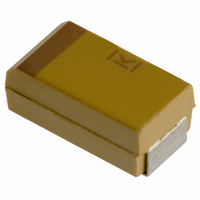
T491B155K025AS Kemet, T491B155K025AS Datasheet - Page 72

T491B155K025AS
Manufacturer Part Number
T491B155K025AS
Description
CAPACITOR TANT 1.5UF 25V 10% SMD
Manufacturer
Kemet
Series
T491r
Type
Moldedr
Datasheet
1.T491B155K025AS.pdf
(100 pages)
Specifications of T491B155K025AS
Capacitance
1.5µF
Voltage - Rated
25V
Tolerance
±10%
Esr (equivalent Series Resistance)
5.000 Ohm
Operating Temperature
-55°C ~ 125°C
Mounting Type
Surface Mount
Package / Case
1210 (3528 Metric)
Size / Dimension
0.138" L x 0.110" W (3.50mm x 2.80mm)
Height
0.075" (1.90mm)
Manufacturer Size Code
B
Features
General Purpose
Lead Free Status / RoHS Status
Contains lead / RoHS non-compliant
Lead Spacing
-
Other names
399-1625-2
70
13.
14.
15.
16.
17.
18.
19.
20.
the vector summation of the capacitive reactance, the
inductive reactance, and the ESR, as illustrated in
Figure 2. As frequency increases, the capacitive reac-
tance decreases. However, the series inductance (L)
shown in Figure 1 produces some inductive reactance,
which increases with frequency. At some frequency, the
impedance ceases to be capacitive and becomes
inductive. This point, at the bottom of the V-shaped
impedance versus frequency curves, is the self-reso-
nant frequency. At the self-resonant frequency, the
reactance is zero, and the impedance consists of the
ESR only. At high frequency more detailed models
apply - See KEMET SPICE models for such instances.
KEMET multilayer ceramic capacitors are shown in
Figures 4, 5, 6 and 7
Thermal Shock:
EIA-198, Method 202, Condition B (5 cycles
-55° to + 125°C).
Life Test:
EIA-198, Method 201, 1000 hours at 200% * of rated
voltage at 125°C. (Except 85°C for Z5U, Y5V & X5R).
Humidity Test:
EIA-198, Method 206, ( Except 1000 hours,85°C,
85% RH, Rated Voltage).
Moisture Resistance:
EIA-198, Method 204, Condition B (20 cycles with
50 volts applied.
Solderability:
EIA-198, Method 301 (245°, 5 secs, Sn62 solder)
95% smooth solder on terminations. See page 14
for recommended profiles.
Resistance to Soldering Heat:
EIA-198, Method 302, Condition B (260°C, 10 sec-
onds) no leaching of nickel barrier.
Terminal Strength:
EIA-198, Method 303, Condition D .
A well constructed multilayer ceramic capacitor chip is
extremely reliable and, for all practical purposes, has no
wearout mechanism when used within the maximum
voltage and temperature ratings. Most failures occur as
a result of mechanical or thermal damage during
mounting on the board, or during subsequent testing.
Capacitor failure may also be induced by sustained
operation at voltages that exceed the rated DC voltage,
voltage spikes or transients that exceed the dielectric's
voltage capability, sustained operation at temperatures
above the maximum rated temperature, internal
defects, or excessive temperature rise due to power
*Note: 150% of rated voltage for selected high capacitance X5R values. Please contact factory.
ENVIRONMENTAL AND PHYSICAL
©KEMET Electronics Corporation, P.O. Box 5928, Greenville, S.C. 29606, (864) 963-6300
Typical impedance versus frequency curves for
See Table 4 on page 71 for limits.
See Table 4 on page 71 for limits.
See Table 4 on page 71 for limits.
RELIABILITY
.
CERAMIC CHIP CAPACITORS
21.
22.
23.
dissipation. As with any practical device, multilayer
ceramic capacitors also possess an inherent, although
low, failure rate when operated within rated conditions.
The primary failure mode is by short-circuit or low insu-
lation resistance, resulting from cracks or from dielectric
breakdown at a defect site. KEMET monitors reliability
with a periodic sampling program for selected values.
Results are available in our FIT (Failure in Time) report
for commercial chips.
Storage and Handling:
working environments. While the chips themselves are
quite robust in other environments, solderability will be
degraded by exposure to high temperatures, high
humidity, corrosive atmospheres, and long term stor-
age. In addition, packaging materials will be degraded
by high temperature – reels may soften or warp, and
tape peel force may increase. KEMET recommends
that maximum storage temperature not exceed 40
degrees C, and maximum storage humidity not exceed
70% relative humidity. In addition, temperature fluctua-
tions should be minimized to avoid condensation on
the parts, and atmospheres should be free of chlorine
and sulfur bearing compounds. For optimized solder-
ability, chip stock should be used promptly, preferably
within 1.5 years of receipt.
Ceramic capacitors, like any other capacitors, may fail if
they are misapplied. Some misapplications include
mechanical damage, such as impact or excessive flex-
ing of the circuit board. Others include severe mounting
or rework cycles that may also introduce thermal shock.
Still others include exposure to excessive voltage, cur-
rent or temperature. If the dielectric layer of the capaci-
tor is damaged by misapplication, the circuit may fail.
The electrical energy of the circuit can be released as
heat, which may damage the circuit board and other
components as well.
Detailed application information can be found in KEMET
Engineering Bulletins.
F-2100
F-2102
F-2105
F-2103
F-2110
F-2111
has SPICE models of most chip capacitors. Models
may be downloaded from KEMET’s website
www.kemet.com.
your KEMET representative for details or post your
questions to KEMET's homepage on the web
http://www.kemet.com.
Ceramic chip capacitors should be stored in normal
For analysis of high frequency applications, KEMET
Additional information is also available - See
ADDITIONAL INFORMATION
Surface Mount-Mounting Pad
Dimensions and Considerations
Reflow Soldering Process
Wave Solder Process
Surface Mount Repair
Capacitance Monitoring while Flex Testing
Ceramic Chip Capacitors “Flex Cracks” -
Understanding and Solutions
MISAPPLICATION


