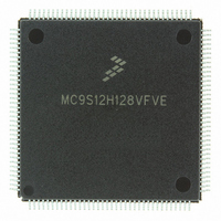
MC9S12H128VFVE Freescale Semiconductor, MC9S12H128VFVE Datasheet - Page 109

MC9S12H128VFVE
Manufacturer Part Number
MC9S12H128VFVE
Description
IC MCU 128K FLASH 16MHZ 144-LQFP
Manufacturer
Freescale Semiconductor
Series
HCS12r
Datasheet
1.MC9S12H256VFVER.pdf
(130 pages)
Specifications of MC9S12H128VFVE
Core Processor
HCS12
Core Size
16-Bit
Speed
16MHz
Connectivity
CAN, I²C, SCI, SPI
Peripherals
LCD, POR, PWM, WDT
Number Of I /o
99
Program Memory Size
128KB (128K x 8)
Program Memory Type
FLASH
Eeprom Size
4K x 8
Ram Size
6K x 8
Voltage - Supply (vcc/vdd)
2.35 V ~ 5.25 V
Data Converters
A/D 8x10b
Oscillator Type
Internal
Operating Temperature
-40°C ~ 105°C
Package / Case
144-LQFP
Processor Series
S12H
Core
HCS12
Data Bus Width
16 bit
Data Ram Size
6 KB
Interface Type
CAN/I2C/SCI/SPI
Maximum Clock Frequency
16 MHz
Number Of Programmable I/os
99
Number Of Timers
8
Operating Supply Voltage
- 0.3 V to + 6 V
Maximum Operating Temperature
+ 105 C
Mounting Style
SMD/SMT
3rd Party Development Tools
EWHCS12
Minimum Operating Temperature
- 40 C
On-chip Adc
16-ch x 10-bit
Package
144LQFP
Family Name
HCS12
Maximum Speed
16 MHz
Lead Free Status / RoHS Status
Lead free / RoHS Compliant
Available stocks
Company
Part Number
Manufacturer
Quantity
Price
Company:
Part Number:
MC9S12H128VFVE
Manufacturer:
Freescale Semiconductor
Quantity:
10 000
A.4.3 Phase Locked Loop
The oscillator provides the reference clock for the PLL. The PLL´s Voltage Controlled Oscillator (VCO)
is also the system clock source in self clock mode.
A.4.3.1 XFC Component Selection
This section describes the selection of the XFC components to achieve a good filter characteristics.
The following procedure can be used to calculate the resistance and capacitance values using typical
values for K
The VCO Gain at the desired VCO output frequency is approximated by:
The phase detector relationship is given by:
i
ch
3. XCLKS =1 during reset
is the current in tracking mode.
1
, f
1
and i
f
osc
ch
from Table A-15.
refdv+1
Figure A-2 Basic PLL functional diagram
1
f
ref
K
V
K
=
K
=
1
f
cmp
i
ch
e
Loop Divider
---------------------- -
Detector
f
K
Phase
1
K
synr+1
1
–
K
V
f
1V
1
vco
C
MC9S12H256 Device User Guide — V01.20
s
VDDPLL
R
1
2
C
p
VCO
K
V
f
vco
109


