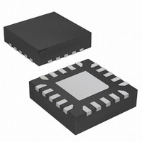
ATTINY24A-MMH Atmel, ATTINY24A-MMH Datasheet - Page 123

ATTINY24A-MMH
Manufacturer Part Number
ATTINY24A-MMH
Description
MCU AVR 2K FLASH 20MHZ 20VQFN
Manufacturer
Atmel
Series
AVR® ATtinyr
Specifications of ATTINY24A-MMH
Core Processor
AVR
Core Size
8-Bit
Speed
20MHz
Connectivity
USI
Peripherals
Brown-out Detect/Reset, POR, PWM, Temp Sensor, WDT
Number Of I /o
12
Program Memory Size
2KB (1K x 16)
Program Memory Type
FLASH
Eeprom Size
128 x 8
Ram Size
128 x 8
Voltage - Supply (vcc/vdd)
1.8 V ~ 5.5 V
Data Converters
A/D 8x10b
Oscillator Type
Internal
Operating Temperature
-40°C ~ 85°C
Package / Case
20-MLF®, QFN
Processor Series
ATTINY2x
Core
AVR8
Data Bus Width
8 bit
Data Ram Size
128 B
Interface Type
SPI, USI
Maximum Clock Frequency
20 MHz
Number Of Programmable I/os
12
Number Of Timers
2
Maximum Operating Temperature
+ 85 C
Mounting Style
SMD/SMT
3rd Party Development Tools
EWAVR, EWAVR-BL
Development Tools By Supplier
ATAVRDRAGON, ATSTK500, ATSTK600, ATAVRISP2, ATAVRONEKIT
Minimum Operating Temperature
- 40 C
On-chip Adc
10 bit, 20 Channel
For Use With
ATSTK505 - ADAPTER KIT FOR 14PIN AVR MCU
Lead Free Status / RoHS Status
Lead free / RoHS Compliant
- Current page: 123 of 286
- Download datasheet (10Mb)
14.4
14.4.1
14.4.2
14.4.3
14.4.4
14.4.5
14.5
14.5.1
8183C–AVR–03/11
Alternative USI Usage
Register Descriptions
Half-Duplex Asynchronous Data Transfer
4-Bit Counter
12-Bit Timer/Counter
Edge Triggered External Interrupt
Software Interrupt
USICR – USI Control Register
The flexible design of the USI allows it to be used for other tasks when serial communication is
not needed. Below are some examples.
Using the USI Data Register in three-wire mode it is possible to implement a more compact and
higher performance UART than by software, only.
The 4-bit counter can be used as a stand-alone counter with overflow interrupt. Note that if the
counter is clocked externally, both clock edges will increment the counter value.
Combining the 4-bit USI counter with one of the 8-bit timer/counters creates a 12-bit counter.
By setting the counter to maximum value (F) it can function as an additional external interrupt.
The Overflow Flag and Interrupt Enable bit are then used for the external interrupt. This feature
is selected by the USICS1 bit.
The counter overflow interrupt can be used as a software interrupt triggered by a clock strobe.
The USI Control Register includes bits for interrupt enable, setting the wire mode, selecting the
clock and clock strobe.
• Bit 7 – USISIE: Start Condition Interrupt Enable
Setting this bit to one enables the start condition detector interrupt. If there is a pending interrupt
and USISIE and the Global Interrupt Enable Flag are set to one the interrupt will be executed
immediately. Refer to the USISIF bit description on
• Bit 6 – USIOIE: Counter Overflow Interrupt Enable
Setting this bit to one enables the counter overflow interrupt. If there is a pending interrupt and
USIOIE and the Global Interrupt Enable Flag are set to one the interrupt will be executed imme-
diately. Refer to the USIOIF bit description on
• Bits 5:4 – USIWM[1:0]: Wire Mode
These bits set the type of wire mode to be used, as shown in
Basically, only the function of the outputs are affected by these bits. Data and clock inputs are
not affected by the mode selected and will always have the same function. The counter and USI
Bit
0x0D (0x2D)
Read/Write
Initial Value
USISIE
R/W
7
0
USIOIE
R/W
6
0
USIWM1
R/W
5
0
USIWM0
R/W
4
0
page 126
page 125
USICS1
R/W
3
0
for further details.
ATtiny24A/44A/84A
Table 14-1 on page
for further details.
USICS0
R/W
2
0
USICLK
W
1
0
USITC
124.
W
0
0
USICR
123
Related parts for ATTINY24A-MMH
Image
Part Number
Description
Manufacturer
Datasheet
Request
R

Part Number:
Description:
Manufacturer:
Atmel Corporation
Datasheet:

Part Number:
Description:
Manufacturer:
Atmel Corporation
Datasheet:

Part Number:
Description:
IC MCU AVR 2K FLASH 20MHZ 20-QFN
Manufacturer:
Atmel
Datasheet:

Part Number:
Description:
IC MCU AVR 2K FLASH 20MHZ 14SOIC
Manufacturer:
Atmel
Datasheet:

Part Number:
Description:
MCU AVR 2K FLASH 15MHZ 20-QFN
Manufacturer:
Atmel
Datasheet:

Part Number:
Description:
IC MCU AVR 2K FLASH 20MHZ 14-DIP
Manufacturer:
Atmel
Datasheet:

Part Number:
Description:
MCU AVR 2KB FLASH 20MHZ 14SOIC
Manufacturer:
Atmel
Datasheet:

Part Number:
Description:
MCU AVR 2KB FLASH 20MHZ 20QFN
Manufacturer:
Atmel
Datasheet:

Part Number:
Description:
MCU AVR 2K FLASH 15MHZ 14-SOIC
Manufacturer:
Atmel
Datasheet:

Part Number:
Description:
DEV KIT FOR AVR/AVR32
Manufacturer:
Atmel
Datasheet:

Part Number:
Description:
INTERVAL AND WIPE/WASH WIPER CONTROL IC WITH DELAY
Manufacturer:
ATMEL Corporation
Datasheet:

Part Number:
Description:
Low-Voltage Voice-Switched IC for Hands-Free Operation
Manufacturer:
ATMEL Corporation
Datasheet:


