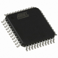
AT80C51RD2-RLRUM Atmel, AT80C51RD2-RLRUM Datasheet - Page 52

AT80C51RD2-RLRUM
Manufacturer Part Number
AT80C51RD2-RLRUM
Description
IC MCU 80C51 HI PERFORM 44VQFP
Manufacturer
Atmel
Series
80Cr
Datasheet
1.AT80C51RD2-RLRUM.pdf
(81 pages)
Specifications of AT80C51RD2-RLRUM
Core Processor
8051
Core Size
8-Bit
Speed
40MHz
Connectivity
UART/USART
Peripherals
POR, PWM, WDT
Number Of I /o
32
Program Memory Type
ROMless
Ram Size
1K x 8
Voltage - Supply (vcc/vdd)
2.7 V ~ 5.5 V
Oscillator Type
Internal
Operating Temperature
-40°C ~ 85°C
Package / Case
44-TQFP, 44-VQFP
Processor Series
AT80x
Core
8051
Data Bus Width
8 bit
Data Ram Size
1280 B
Interface Type
UART, SPI
Maximum Clock Frequency
60 MHz
Number Of Programmable I/os
32
Number Of Timers
3
Operating Supply Voltage
2.7 V to 5.5 V
Maximum Operating Temperature
+ 85 C
Mounting Style
SMD/SMT
3rd Party Development Tools
PK51, CA51, A51, ULINK2
Minimum Operating Temperature
- 40 C
Lead Free Status / RoHS Status
Lead free / RoHS Compliant
Eeprom Size
-
Program Memory Size
-
Data Converters
-
Lead Free Status / Rohs Status
Details
Available stocks
Company
Part Number
Manufacturer
Quantity
Price
Company:
Part Number:
AT80C51RD2-RLRUM
Manufacturer:
NXP
Quantity:
8 243
13. Keyboard Interface
13.0.1
13.0.2
52
AT80C51RD2
Interrupt
Power Reduction Mode
The AT80C51RD2 implement a keyboard interface allowing the connection of a 8 x n matrix key-
board. It is based on 8 inputs with programmable interrupt capability on both high or low level.
These inputs are available as alternate function of P1 and allow to exit from idle and power-
down modes.
The keyboard interfaces with the C51 core through 3 special function registers: KBLS, the Key-
board Level Selection register (Table 13-3), KBE, The Keyboard Interrupt Enable register
(Table 13-2), and KBF, the Keyboard Flag register (Table 13-1).
The keyboard inputs are considered as 8 independent interrupt sources sharing the same inter-
rupt vector. An interrupt enable bit (KBD in IE1) allows global enable or disable of the keyboard
interrupt (see Figure 13-1). As detailed in Figure 13-2 each keyboard input has the capability to
detect a programmable level according to KBLS.x bit value. Level detection is then reported in
interrupt flags KBF.x that can be masked by software using KBE.x bits.
This structure allow keyboard arrangement from 1 x n to 8 x n matrix and allows usage of P1
inputs for other purpose.
Figure 13-1. Keyboard Interface Block Diagram
Figure 13-2. Keyboard Input Circuitry
P1 inputs allow exit from idle and power-down modes as detailed in Section “Power-down
Mode”, page 56.
P1:x
P1.0
P1.1
P1.2
P1.3
P1.4
P1.5
P1.6
P1.7
V
CC
Internal Pull-up
Input Circuitry
Input Circuitry
Input Circuitry
Input Circuitry
Input Circuitry
Input Circuitry
Input Circuitry
Input Circuitry
KBLS.x
0
1
KBF.x
KBE.x
KBD
IE1
Keyboard Interface
Interrupt Request
KBDIT
4113D–8051–01/09


