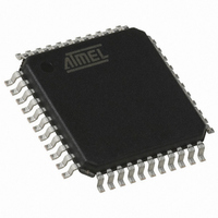
AT89C51RE2-RLTUM Atmel, AT89C51RE2-RLTUM Datasheet - Page 185

AT89C51RE2-RLTUM
Manufacturer Part Number
AT89C51RE2-RLTUM
Description
MCU 8051 128K FLASH 44-VQFP
Manufacturer
Atmel
Series
89Cr
Datasheet
1.AT89C51RE2-SLSUM.pdf
(187 pages)
Specifications of AT89C51RE2-RLTUM
Core Processor
8051
Core Size
8-Bit
Speed
60MHz
Connectivity
I²C, SPI, UART/USART
Peripherals
POR, PWM, WDT
Number Of I /o
34
Program Memory Size
128KB (128K x 8)
Program Memory Type
FLASH
Ram Size
8K x 8
Voltage - Supply (vcc/vdd)
2.7 V ~ 5.5 V
Oscillator Type
External
Operating Temperature
-40°C ~ 85°C
Package / Case
44-TQFP, 44-VQFP
Processor Series
AT89x
Core
8051
Data Bus Width
8 bit
Data Ram Size
8 KB
Interface Type
UART, SPI
Maximum Clock Frequency
60 MHz
Number Of Programmable I/os
34
Number Of Timers
3
Operating Supply Voltage
2.7 V to 5.5 V
Maximum Operating Temperature
+ 85 C
Mounting Style
SMD/SMT
3rd Party Development Tools
PK51, CA51, A51, ULINK2
Development Tools By Supplier
AT89OCD-01
Minimum Operating Temperature
- 40 C
Height
1.45 mm
Length
10.1 mm
Supply Voltage (max)
5.5 V
Supply Voltage (min)
2.7 V
Width
10.1 mm
For Use With
AT89STK-11 - KIT STARTER FOR AT89C51RX2
Lead Free Status / RoHS Status
Lead free / RoHS Compliant
Eeprom Size
-
Data Converters
-
Lead Free Status / Rohs Status
Details
Available stocks
Company
Part Number
Manufacturer
Quantity
Price
Company:
Part Number:
AT89C51RE2-RLTUM
Manufacturer:
MSC
Quantity:
1 560
7663E–8051–10/08
Timer 2 ................................................................................................. 77
Programmable Counter Array PCA ................................................... 82
Serial I/O Port ...................................................................................... 94
Interrupt System ............................................................................... 109
Power Management .......................................................................... 118
Oscillator ........................................................................................... 122
Hardware Watchdog Timer .............................................................. 124
Reduced EMI Mode ........................................................................... 126
Keyboard Interface ........................................................................... 127
Interrupt .............................................................................................................. 71
Registers............................................................................................................. 73
Auto-Reload Mode.............................................................................................. 77
Programmable Clock-Output .............................................................................. 78
Registers............................................................................................................. 80
PCA Capture Mode............................................................................................. 90
16-bit Software Timer/ Compare Mode............................................................... 90
High Speed Output Mode ................................................................................... 91
Pulse Width Modulator Mode.............................................................................. 92
PCA Watchdog Timer ......................................................................................... 93
Framing Error Detection ..................................................................................... 94
Automatic Address Recognition.......................................................................... 95
Registers............................................................................................................. 97
Baud Rate Selection for UART 0 for Mode 1 and 3............................................ 98
Baud Rate Selection for UART 1 for Mode 1 and 3............................................ 99
UART Registers................................................................................................ 103
Registers........................................................................................................... 110
Interrupt Sources and Vector Addresses.......................................................... 117
Introduction ....................................................................................................... 118
Idle Mode .......................................................................................................... 118
Power-Down Mode ........................................................................................... 118
Registers........................................................................................................... 121
Registers........................................................................................................... 122
Functional Block Diagram .................................................................................123
Using the WDT ................................................................................................. 124
WDT During Power Down and Idle................................................................... 125
Registers........................................................................................................... 128
AT89C51RE2
2


