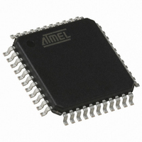
AT89C51RE2-RLTUM Atmel, AT89C51RE2-RLTUM Datasheet - Page 67

AT89C51RE2-RLTUM
Manufacturer Part Number
AT89C51RE2-RLTUM
Description
MCU 8051 128K FLASH 44-VQFP
Manufacturer
Atmel
Series
89Cr
Datasheet
1.AT89C51RE2-SLSUM.pdf
(187 pages)
Specifications of AT89C51RE2-RLTUM
Core Processor
8051
Core Size
8-Bit
Speed
60MHz
Connectivity
I²C, SPI, UART/USART
Peripherals
POR, PWM, WDT
Number Of I /o
34
Program Memory Size
128KB (128K x 8)
Program Memory Type
FLASH
Ram Size
8K x 8
Voltage - Supply (vcc/vdd)
2.7 V ~ 5.5 V
Oscillator Type
External
Operating Temperature
-40°C ~ 85°C
Package / Case
44-TQFP, 44-VQFP
Processor Series
AT89x
Core
8051
Data Bus Width
8 bit
Data Ram Size
8 KB
Interface Type
UART, SPI
Maximum Clock Frequency
60 MHz
Number Of Programmable I/os
34
Number Of Timers
3
Operating Supply Voltage
2.7 V to 5.5 V
Maximum Operating Temperature
+ 85 C
Mounting Style
SMD/SMT
3rd Party Development Tools
PK51, CA51, A51, ULINK2
Development Tools By Supplier
AT89OCD-01
Minimum Operating Temperature
- 40 C
Height
1.45 mm
Length
10.1 mm
Supply Voltage (max)
5.5 V
Supply Voltage (min)
2.7 V
Width
10.1 mm
For Use With
AT89STK-11 - KIT STARTER FOR AT89C51RX2
Lead Free Status / RoHS Status
Lead free / RoHS Compliant
Eeprom Size
-
Data Converters
-
Lead Free Status / Rohs Status
Details
Available stocks
Company
Part Number
Manufacturer
Quantity
Price
Company:
Part Number:
AT89C51RE2-RLTUM
Manufacturer:
MSC
Quantity:
1 560
Start Application
ISP Command
summary
UART Protocol frames
Table 44. Summary of frames from Host
Address Mapping
7663E–8051–10/08
Command
Program selected memory
Start application with watchdog
Select New Page
Select Memory
Read selected memory
Blank Check selected memory
Erase Selected memory
The start application command is used to quit the bootloader and start the application loaded.
The start application is performed by a watchdog reset.
The best way to start the application from a user defined entry point is to configure the FCB
(Fuse Configuration Byte) before launching the watchdog. Then, depending on the configuration
of the BRV2:0 field, the hardware boots from the selected memory area.
Table 45. Memory Families, Addresses & Coding
Attempting an access with any other ‘coding’, ‘page number’ or ‘Address’ results in no action
and no answer from the bootloader.
Memory/Parameter
Bootloader revision
Record
Type
Product name
00h
01h
02h
04h
Manuf. code
Family code
Product rev
Boot id1
Boot id2
FLASH
HSB
FCB
nb of data
Record
Length
00h
02h
02h
05h
address
address
Offset
0000h
0000h
0000h
start
start
coding
8
3
6
0
7
bits) + 0h
Data[0]
Memory
Page (4
0 up to 0x1FFFF
space
00h
x
x
Start Address
Address
00h
01h
02h
30h
31h
60h
61h
0
0
Data[1]
Page
FFh
00h
x
x
Page number
0 up to 1
Data[2]
00h
0
0
0
0
x
x
x
x
End Address
AT89C51RE2
Data[3]
FLASH
SECURITY
CONFIGURATION
BOOTLOADER
SIGNATURE
Memory/Information
00h
x
x
x
x
Family
Data[4]
00h
01h
02h
x
x
x
x
67


