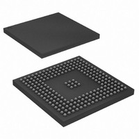
AT91SAM9XE256-CU Atmel, AT91SAM9XE256-CU Datasheet - Page 320

AT91SAM9XE256-CU
Manufacturer Part Number
AT91SAM9XE256-CU
Description
MCU ARM9 256K FLASH 217-BGA
Manufacturer
Atmel
Series
AT91SAMr
Specifications of AT91SAM9XE256-CU
Core Processor
ARM9
Core Size
16/32-Bit
Speed
180MHz
Connectivity
EBI/EMI, Ethernet, I²C, MMC, SPI, SSC, UART/USART, USB
Peripherals
Brown-out Detect/Reset, POR, PWM, WDT
Number Of I /o
96
Program Memory Size
256KB (256K x 8)
Program Memory Type
FLASH
Ram Size
56K x 8
Voltage - Supply (vcc/vdd)
1.65 V ~ 1.95 V
Data Converters
A/D 4x10b
Oscillator Type
Internal
Operating Temperature
-40°C ~ 85°C
Package / Case
217-LFBGA
Processor Series
AT91SAMx
Core
ARM926EJ-S
Data Bus Width
32 bit
Data Ram Size
32 KB
Interface Type
2-Wire, EBI, I2S, SPI, USART
Maximum Clock Frequency
180 MHz
Number Of Programmable I/os
96
Number Of Timers
6
Maximum Operating Temperature
+ 85 C
Mounting Style
SMD/SMT
3rd Party Development Tools
JTRACE-ARM-2M, KSK-AT91SAM9XE-PL, MDK-ARM, RL-ARM, ULINK2
Development Tools By Supplier
AT91SAM-ICE, AT91-ISP, AT91SAM9XE-EK
Minimum Operating Temperature
- 40 C
On-chip Adc
10 bit, 4 Channel
Package
217LFBGA
Device Core
ARM926EJ-S
Family Name
91S
Maximum Speed
180 MHz
Operating Supply Voltage
1.8|2.5|3.3 V
For Use With
AT91SAM9XE-EK - KIT EVAL FOR AT91SAM9XEAT91SAM-ICE - EMULATOR FOR AT91 ARM7/ARM9
Lead Free Status / RoHS Status
Lead free / RoHS Compliant
Eeprom Size
-
Lead Free Status / Rohs Status
Lead free / RoHS Compliant
Available stocks
Company
Part Number
Manufacturer
Quantity
Price
Company:
Part Number:
AT91SAM9XE256-CU
Manufacturer:
ATMEL
Quantity:
215
- Current page: 320 of 860
- Download datasheet (13Mb)
28. Power Management Controller (PMC)
28.1
6254C–ATARM–22-Jan-10
Description
The Power Management Controller (PMC) optimizes power consumption by controlling all sys-
tem and user peripheral clocks. The PMC enables/disables the clock inputs to many of the
peripherals and the ARM Processor.
The Power Management Controller provides the following clocks:
Figure 28-1. AT91SAM9XE128/256/512 Power Management Controller Block Diagram
• MCK, the Master Clock, programmable from a few hundred Hz to the maximum operating
• Processor Clock (PCK), must be switched off when entering processor in Idle Mode.
• Peripheral Clocks, typically MCK, provided to the embedded peripherals (USART, SSC, SPI,
• UHP Clock (UHPCK), required by USB Host Port operations.
• Programmable Clock Outputs can be selected from the clocks provided by the clock
• Five flexible operating modes:
frequency of the device. It is available to the modules running permanently, such as the AIC
and the Memory Controller.
TWI, TC, MCI, etc.) and independently controllable. In order to reduce the number of clock
names in a product, the Peripheral Clocks are named MCK in the product datasheet.
generator and driven on the PCKx pins.
– Normal Mode, processor and peripherals running at a programmable frequency
– Idle Mode, processor stopped waiting for an interrupt
– Slow Clock Mode, processor and peripherals running at low frequency
– Standby Mode, mix of Idle and Backup Mode, peripheral running at low frequency,
– Backup Mode, Main Power Supplies off, VDDBU powered by a battery
processor stopped waiting for an interrupt
PLLBCK
MAINCK
PLLACK
SLCK
Master Clock Controller
AT91SAM9XE128/256/512 Preliminary
/1,/2,/4,...,/64
Prescaler
MAINCK
PLLBCK
PLLACK
PLLBCK
SLCK
Programmable Clock Controller
Divider
/1,/2,/4
USB Clock Controller
Divider
/1,/2,/4
/1,/2,/4,...,/64
Prescaler
Clock Controller
Processor
Controller
ON/OFF
Idle Mode
ON/OFF
Clock
Peripherals
ON/OFF
PCK
int
MCK
periph_clk[..]
pck[..]
UDPCK
UHPCK
320
Related parts for AT91SAM9XE256-CU
Image
Part Number
Description
Manufacturer
Datasheet
Request
R

Part Number:
Description:
KIT EVAL FOR AT91SAM9XE
Manufacturer:
Atmel
Datasheet:

Part Number:
Description:
MCU ARM9 64K SRAM 144-LFBGA
Manufacturer:
Atmel
Datasheet:

Part Number:
Description:
IC ARM7 MCU FLASH 256K 100LQFP
Manufacturer:
Atmel
Datasheet:

Part Number:
Description:
IC ARM9 MPU 217-LFBGA
Manufacturer:
Atmel
Datasheet:

Part Number:
Description:
MCU ARM9 ULTRA LOW PWR 217-LFBGA
Manufacturer:
Atmel
Datasheet:

Part Number:
Description:
MCU ARM9 324-TFBGA
Manufacturer:
Atmel
Datasheet:

Part Number:
Description:
IC MCU ARM9 SAMPLING 217CBGA
Manufacturer:
Atmel
Datasheet:

Part Number:
Description:
IC ARM9 MCU 217-LFBGA
Manufacturer:
Atmel
Datasheet:

Part Number:
Description:
IC ARM9 MCU 208-PQFP
Manufacturer:
Atmel
Datasheet:

Part Number:
Description:
MCU ARM 512K HS FLASH 100-LQFP
Manufacturer:
Atmel
Datasheet:

Part Number:
Description:
MCU ARM 512K HS FLASH 100-TFBGA
Manufacturer:
Atmel
Datasheet:

Part Number:
Description:
IC ARM9 MCU 200 MHZ 324-TFBGA
Manufacturer:
Atmel
Datasheet:

Part Number:
Description:
IC ARM MCU 16BIT 128K 256BGA
Manufacturer:
Atmel
Datasheet:

Part Number:
Description:
IC ARM7 MCU 32BIT 128K 64LQFP
Manufacturer:
Atmel
Datasheet:

Part Number:
Description:
IC ARM7 MCU FLASH 256K 128-LQFP
Manufacturer:
Atmel
Datasheet:


