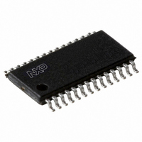
P89LPC938FDH,529 NXP Semiconductors, P89LPC938FDH,529 Datasheet - Page 49

P89LPC938FDH,529
Manufacturer Part Number
P89LPC938FDH,529
Description
IC 80C51 MCU FLASH 8K 28-TSSOP
Manufacturer
NXP Semiconductors
Series
LPC900r
Datasheet
1.P89LPC938FHN151.pdf
(68 pages)
Specifications of P89LPC938FDH,529
Program Memory Type
FLASH
Program Memory Size
8KB (8K x 8)
Package / Case
28-TSSOP
Core Processor
8051
Core Size
8-Bit
Speed
18MHz
Connectivity
I²C, SPI, UART/USART
Peripherals
Brown-out Detect/Reset, LED, POR, PWM, WDT
Number Of I /o
26
Eeprom Size
512 x 8
Ram Size
768 x 8
Voltage - Supply (vcc/vdd)
2.4 V ~ 3.6 V
Data Converters
A/D 8x10b
Oscillator Type
Internal
Operating Temperature
-40°C ~ 85°C
Processor Series
P89LPC9x
Core
80C51
Data Bus Width
8 bit
Data Ram Size
256 B
Interface Type
I2C/SPI/UART
Maximum Clock Frequency
18 MHz
Number Of Programmable I/os
26
Number Of Timers
2
Operating Supply Voltage
2.4 V to 3.6 V
Maximum Operating Temperature
+ 85 C
Mounting Style
SMD/SMT
3rd Party Development Tools
PK51, CA51, A51, ULINK2
Minimum Operating Temperature
- 40 C
On-chip Adc
8-ch x 10-bit
Lead Free Status / RoHS Status
Lead free / RoHS Compliant
For Use With
622-1014 - BOARD FOR LPC9XX TSSOP622-1011 - BOARD FOR LPC938 TSSOP622-1008 - BOARD FOR LPC9103 10-HVSON622-1006 - SOCKET ADAPTER BOARDMCB900K - BOARD PROTOTYPE NXP 89LPC9EPM900K - EMULATOR/PROGRAMMER NXP P89LPC9568-4000 - DEMO BOARD SPI/I2C TO DUAL UART568-3510 - DEMO BOARD SPI/I2C TO UART568-1759 - EMULATOR DEBUGGER/PROGRMMR LPC9X568-1758 - BOARD EVAL FOR LPC93X MCU FAMILY
Lead Free Status / Rohs Status
Lead free / RoHS Compliant
Other names
568-2013-5
935278546529
P89LPC938FDH-S
935278546529
P89LPC938FDH-S
Philips Semiconductors
9397 750 14051
Product data sheet
8.7 Clock divider
8.8 Power-down and Idle mode
criteria, the boundary limits will again be compared after all 8 MSBs have been converted.
A boundary status register (BNDSTA0) flags the channels which caused a boundary
interrupt.
The A/D converter requires that its internal clock source be in the range of 500 kHz to
3 MHz to maintain accuracy. A programmable clock divider that divides the clock
from 1 to 8 is provided for this purpose.
In Idle mode the A/D converter, if enabled, will continue to function and can cause the
device to exit Idle mode when the conversion is completed if the A/D interrupt is enabled.
In Power-down mode or Total Power-down mode, the A/D does not function. If the A/D is
enabled, it will consume power. Power can be reduced by disabling the A/D.
Rev. 01 — 25 February 2005
8-bit microcontroller with 10-bit A/D converter
© Koninklijke Philips Electronics N.V. 2005. All rights reserved.
P89LPC938
49 of 68


