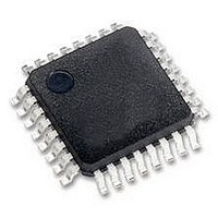
MCHC908GR8AMFAER Freescale Semiconductor, MCHC908GR8AMFAER Datasheet - Page 207

MCHC908GR8AMFAER
Manufacturer Part Number
MCHC908GR8AMFAER
Description
IC MCU 8K FLASH 8MHZ 32-LQFP
Manufacturer
Freescale Semiconductor
Series
HC08r
Specifications of MCHC908GR8AMFAER
Core Processor
HC08
Core Size
8-Bit
Speed
8MHz
Connectivity
SCI, SPI
Peripherals
LVD, POR, PWM
Number Of I /o
21
Program Memory Size
7.5KB (7.5K x 8)
Program Memory Type
FLASH
Ram Size
384 x 8
Voltage - Supply (vcc/vdd)
2.7 V ~ 5.5 V
Data Converters
A/D 6x8b
Oscillator Type
Internal
Operating Temperature
-40°C ~ 125°C
Package / Case
32-LQFP
Controller Family/series
HC08
No. Of I/o's
21
Ram Memory Size
384Byte
Cpu Speed
8MHz
No. Of Timers
2
Embedded Interface Type
I2C, SCI, SPI
Rohs Compliant
Yes
Processor Series
HC08G
Core
HC08
Data Bus Width
8 bit
Data Ram Size
384 B
Interface Type
SCI, SPI
Maximum Clock Frequency
8.2 MHz
Number Of Programmable I/os
21
Number Of Timers
3
Maximum Operating Temperature
+ 125 C
Mounting Style
SMD/SMT
Development Tools By Supplier
FSICEBASE, DEMO908GZ60E, M68CBL05CE, M68EML08GPGTE
Minimum Operating Temperature
- 40 C
On-chip Adc
8 bit, 6 Channel
Lead Free Status / RoHS Status
Lead free / RoHS Compliant
Eeprom Size
-
Lead Free Status / Rohs Status
Details
Available stocks
Company
Part Number
Manufacturer
Quantity
Price
Company:
Part Number:
MCHC908GR8AMFAER
Manufacturer:
Freescale Semiconductor
Quantity:
10 000
- Current page: 207 of 292
- Download datasheet (4Mb)
In this case, an overflow can be missed easily. Since no more SPRF interrupts can be generated until this
OVRF is serviced, it is not obvious that bytes are being lost as more transmissions are completed. To
prevent this, either enable the OVRF interrupt or do another read of the SPSCR following the read of the
SPDR. This ensures that the OVRF was not set before the SPRF was cleared and that future
transmissions can set the SPRF bit.
SPSCR read, enable the OVRF to the CPU by setting the ERRIE bit.
16.6.2 Mode Fault Error
Setting SPMSTR selects master mode and configures the SPSCK and MOSI pins as outputs and the
MISO pin as an input. Clearing SPMSTR selects slave mode and configures the SPSCK and MOSI pins
as inputs and the MISO pin as an output. The mode fault bit, MODF, becomes set any time the state of
the slave select pin, SS, is inconsistent with the mode selected by SPMSTR.
To prevent SPI pin contention and damage to the MCU, a mode fault error occurs if:
For the MODF flag to be set, the mode fault error enable bit (MODFEN) must be set. Clearing the
MODFEN bit does not clear the MODF flag but does prevent MODF from being set again after MODF is
cleared.
MODF generates a receiver/error CPU interrupt request if the error interrupt enable bit (ERRIE) is also
set. The SPRF, MODF, and OVRF interrupts share the same CPU interrupt vector. (See
It is not possible to enable MODF or OVRF individually to generate a receiver/error CPU interrupt request.
However, leaving MODFEN low prevents MODF from being set.
Freescale Semiconductor
•
•
The SS pin of a slave SPI goes high during a transmission
The SS pin of a master SPI goes low at any time
SPI RECEIVE
COMPLETE
Figure 16-11. Clearing SPRF When OVRF Interrupt Is Not Enabled
SPSCR
OVRF
READ
READ
SPDR
SPRF
MC68HC908GT16 • MC68HC908GT8 • MC68HC08GT16 Data Sheet, Rev. 5.0
1
2
3
4
5
6
7
BYTE 1
BYTE 2 SETS SPRF BIT.
CPU READS SPSCR WITH SPRF BIT SET
AND OVRF BIT CLEAR.
BYTE 3 SETS OVRF BIT. BYTE 3 IS LOST.
BYTE 1 SETS SPRF BIT.
CPU READS SPSCR WITH SPRF BIT SET
AND OVRF BIT CLEAR.
CPU READS BYTE 1 IN SPDR,
CLEARING SPRF BIT.
CPU READS SPSCR AGAIN
TO CHECK OVRF BIT.
1
2
3
Figure 16-11
4
BYTE 2
5
illustrates this process. Generally, to avoid this second
BYTE 3
6
7
8
10
11
12
13
14
8
9
CPU READS SPSCR AGAIN
TO CHECK OVRF BIT.
CPU READS BYTE 2 SPDR,
CLEARING OVRF BIT.
BYTE 4 SETS SPRF BIT.
CPU READS SPSCR.
CPU READS BYTE 4 IN SPDR,
CLEARING SPRF BIT.
CPU READS SPSCR AGAIN
TO CHECK OVRF BIT.
CPU READS BYTE 2 IN SPDR,
CLEARING SPRF BIT.
9
BYTE 4
10
11
12
13
14
Error Conditions
Figure
16-12.)
207
Related parts for MCHC908GR8AMFAER
Image
Part Number
Description
Manufacturer
Datasheet
Request
R
Part Number:
Description:
Manufacturer:
Freescale Semiconductor, Inc
Datasheet:
Part Number:
Description:
Manufacturer:
Freescale Semiconductor, Inc
Datasheet:
Part Number:
Description:
Manufacturer:
Freescale Semiconductor, Inc
Datasheet:
Part Number:
Description:
Manufacturer:
Freescale Semiconductor, Inc
Datasheet:
Part Number:
Description:
Manufacturer:
Freescale Semiconductor, Inc
Datasheet:
Part Number:
Description:
Manufacturer:
Freescale Semiconductor, Inc
Datasheet:
Part Number:
Description:
Manufacturer:
Freescale Semiconductor, Inc
Datasheet:
Part Number:
Description:
Manufacturer:
Freescale Semiconductor, Inc
Datasheet:
Part Number:
Description:
Manufacturer:
Freescale Semiconductor, Inc
Datasheet:
Part Number:
Description:
Manufacturer:
Freescale Semiconductor, Inc
Datasheet:
Part Number:
Description:
Manufacturer:
Freescale Semiconductor, Inc
Datasheet:
Part Number:
Description:
Manufacturer:
Freescale Semiconductor, Inc
Datasheet:
Part Number:
Description:
Manufacturer:
Freescale Semiconductor, Inc
Datasheet:
Part Number:
Description:
Manufacturer:
Freescale Semiconductor, Inc
Datasheet:
Part Number:
Description:
Manufacturer:
Freescale Semiconductor, Inc
Datasheet:


