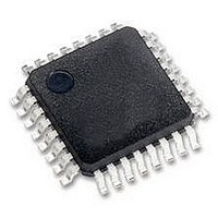
MCHC908GR8AMFAER Freescale Semiconductor, MCHC908GR8AMFAER Datasheet - Page 89

MCHC908GR8AMFAER
Manufacturer Part Number
MCHC908GR8AMFAER
Description
IC MCU 8K FLASH 8MHZ 32-LQFP
Manufacturer
Freescale Semiconductor
Series
HC08r
Specifications of MCHC908GR8AMFAER
Core Processor
HC08
Core Size
8-Bit
Speed
8MHz
Connectivity
SCI, SPI
Peripherals
LVD, POR, PWM
Number Of I /o
21
Program Memory Size
7.5KB (7.5K x 8)
Program Memory Type
FLASH
Ram Size
384 x 8
Voltage - Supply (vcc/vdd)
2.7 V ~ 5.5 V
Data Converters
A/D 6x8b
Oscillator Type
Internal
Operating Temperature
-40°C ~ 125°C
Package / Case
32-LQFP
Controller Family/series
HC08
No. Of I/o's
21
Ram Memory Size
384Byte
Cpu Speed
8MHz
No. Of Timers
2
Embedded Interface Type
I2C, SCI, SPI
Rohs Compliant
Yes
Processor Series
HC08G
Core
HC08
Data Bus Width
8 bit
Data Ram Size
384 B
Interface Type
SCI, SPI
Maximum Clock Frequency
8.2 MHz
Number Of Programmable I/os
21
Number Of Timers
3
Maximum Operating Temperature
+ 125 C
Mounting Style
SMD/SMT
Development Tools By Supplier
FSICEBASE, DEMO908GZ60E, M68CBL05CE, M68EML08GPGTE
Minimum Operating Temperature
- 40 C
On-chip Adc
8 bit, 6 Channel
Lead Free Status / RoHS Status
Lead free / RoHS Compliant
Eeprom Size
-
Lead Free Status / Rohs Status
Details
Available stocks
Company
Part Number
Manufacturer
Quantity
Price
Company:
Part Number:
MCHC908GR8AMFAER
Manufacturer:
Freescale Semiconductor
Quantity:
10 000
- Current page: 89 of 292
- Download datasheet (4Mb)
7.4.1 Switching Clock Sources
The key point to remember in this flow is that the clock source cannot be switched (CS cannot be written)
unless the desired clock is on and stable. A short assembly code example of how to employ this flow is
shown in
;* Clock Switching Code Example
;* This code switches from internal to external clock
;* Clock monitor and interrupts are not enabled
;*
SwitchItoE:
7.4.2 Enabling the Clock Monitor
Many applications require the clock monitor to determine if one of the clock sources has become inactive,
so the other can be used to recover from a potentially dangerous situation. Using the clock monitor
requires both clocks to be active (ECGON and ICGON both set). To enable the clock monitor, both clocks
also must be stable (ECGS and ICGS both set). This is to prevent the use of the clock monitor when a
clock is first turned on and potentially unstable.
Enabling the clock monitor and clock monitor interrupts requires a flow similar to this:
These events must happen in sequence. A short assembly code example of how to employ this flow is
shown in
Freescale Semiconductor
•
•
•
•
•
•
•
•
•
•
ICG Clock Switch
Switching from one clock source to another requires both clock sources to be enabled and stable.
A simple flow requires:
Enable desired clock source
Wait for it to become stable
Switch clocks
Disable previous clock source
Enable the alternate clock source
Wait for both clock sources to be stable
Switch to the desired clock source if necessary
Enable the clock monitor
Enable clock monitor interrupts
Figure
Figure
bset
brclr
bset
bclr
7-9.
7-10.
MC68HC908GT16 • MC68HC908GT8 • MC68HC08GT16 Data Sheet, Rev. 5.0
ECGON,ICGCR
ECGS,ICGCR,*
CS,ICGCR
ICGON,ICGCR
Figure 7-9. Code Example for Switching Clock Sources
; turn on external oscillator
; wait until external clock engaged
; select external clock for bus
; turn off internal clock (if desired)
Usage Notes
89
Related parts for MCHC908GR8AMFAER
Image
Part Number
Description
Manufacturer
Datasheet
Request
R
Part Number:
Description:
Manufacturer:
Freescale Semiconductor, Inc
Datasheet:
Part Number:
Description:
Manufacturer:
Freescale Semiconductor, Inc
Datasheet:
Part Number:
Description:
Manufacturer:
Freescale Semiconductor, Inc
Datasheet:
Part Number:
Description:
Manufacturer:
Freescale Semiconductor, Inc
Datasheet:
Part Number:
Description:
Manufacturer:
Freescale Semiconductor, Inc
Datasheet:
Part Number:
Description:
Manufacturer:
Freescale Semiconductor, Inc
Datasheet:
Part Number:
Description:
Manufacturer:
Freescale Semiconductor, Inc
Datasheet:
Part Number:
Description:
Manufacturer:
Freescale Semiconductor, Inc
Datasheet:
Part Number:
Description:
Manufacturer:
Freescale Semiconductor, Inc
Datasheet:
Part Number:
Description:
Manufacturer:
Freescale Semiconductor, Inc
Datasheet:
Part Number:
Description:
Manufacturer:
Freescale Semiconductor, Inc
Datasheet:
Part Number:
Description:
Manufacturer:
Freescale Semiconductor, Inc
Datasheet:
Part Number:
Description:
Manufacturer:
Freescale Semiconductor, Inc
Datasheet:
Part Number:
Description:
Manufacturer:
Freescale Semiconductor, Inc
Datasheet:
Part Number:
Description:
Manufacturer:
Freescale Semiconductor, Inc
Datasheet:


