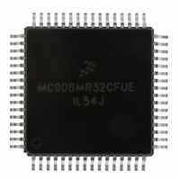
MC908MR32CFUE Freescale Semiconductor, MC908MR32CFUE Datasheet - Page 140

MC908MR32CFUE
Manufacturer Part Number
MC908MR32CFUE
Description
IC MCU 8MHZ 32K FLASH 64-QFP
Manufacturer
Freescale Semiconductor
Series
HC08r
Datasheet
1.MC908MR16CFUE.pdf
(282 pages)
Specifications of MC908MR32CFUE
Core Processor
HC08
Core Size
8-Bit
Speed
8MHz
Connectivity
SCI, SPI
Peripherals
LVD, POR, PWM
Number Of I /o
44
Program Memory Size
32KB (32K x 8)
Program Memory Type
FLASH
Ram Size
768 x 8
Voltage - Supply (vcc/vdd)
4.5 V ~ 5.5 V
Data Converters
A/D 10x10b
Oscillator Type
Internal
Operating Temperature
-40°C ~ 85°C
Package / Case
64-QFP
Processor Series
HC08MR
Core
HC08
Data Bus Width
8 bit
Data Ram Size
768 B
Interface Type
SCI/SPI
Maximum Clock Frequency
8.2 MHz
Number Of Programmable I/os
44
Number Of Timers
6
Operating Supply Voltage
0 V to 5 V
Maximum Operating Temperature
+ 85 C
Mounting Style
SMD/SMT
Development Tools By Supplier
FSICEBASE, M68CBL05CE
Minimum Operating Temperature
- 40 C
On-chip Adc
10-ch x 10-bit
Lead Free Status / RoHS Status
Lead free / RoHS Compliant
Eeprom Size
-
Lead Free Status / Rohs Status
Lead free / RoHS Compliant
Available stocks
Company
Part Number
Manufacturer
Quantity
Price
Company:
Part Number:
MC908MR32CFUE
Manufacturer:
Freescale Semiconductor
Quantity:
10 000
Part Number:
MC908MR32CFUE
Manufacturer:
NXP/恩智浦
Quantity:
20 000
- Current page: 140 of 282
- Download datasheet (2Mb)
Pulse-Width Modulator for Motor Control (PWMMC)
IIf prior to a vector fetch, the interrupt request latch is cleared by one of the actions listed, a CPU interrupt
will no longer be requested. A vector fetch does not alter the state of the PWMs, the FFLAGx event flag,
or FINTx.
12.6.1.3 Manual Mode
In manual mode, the PWM(s) are disabled immediately once a filtered fault condition is detected (logic
high). The PWM(s) remain disabled until software clears the corresponding FFLAGx event bit and a new
PWM cycle begins. In manual mode, the fault pins are grouped in pairs, each pair sharing common
functionality. A fault condition on pins 1 and 3 may be cleared, allowing the PWM(s) to enable at the start
of a PWM cycle regardless of the logic level at the fault pin. See
and 4 can only be cleared, allowing the PWM(s) to enable, if a logic low level at the fault pin is present at
the start of a PWM cycle. See
The function of the fault control and event bits is the same as in automatic mode except that the PWMs
are not re-enabled until the FFLAGx event bit is cleared by writing to the FTACKx bit and the filtered fault
condition is cleared (logic low).
140
FILTERED FAULT PIN
FILTERED FAULT PIN 1 OR 3
If the FFLAGx or FINTx bits are not cleared during the interrupt service
routine, the interrupt request latch will not be cleared.
PWM(S) ENABLED
PWM(S) ENABLED
Figure 12-29. PWM Disabling in Manual Mode (Example 1)
Figure 12-28. PWM Disabling in Automatic Mode
MC68HC908MR32 • MC68HC908MR16 Data Sheet, Rev. 6.1
Figure
12-30.
PWM(S) DISABLED
FFLAGX CLEARED
PWM(S) DISABLED (INACTIVE)
NOTE
Figure
PWM(S) ENABLED
12-29. A fault condition on pins 2
PWM(S) ENABLED
Freescale Semiconductor
Related parts for MC908MR32CFUE
Image
Part Number
Description
Manufacturer
Datasheet
Request
R
Part Number:
Description:
Manufacturer:
Freescale Semiconductor, Inc
Datasheet:
Part Number:
Description:
Manufacturer:
Freescale Semiconductor, Inc
Datasheet:
Part Number:
Description:
Manufacturer:
Freescale Semiconductor, Inc
Datasheet:
Part Number:
Description:
Manufacturer:
Freescale Semiconductor, Inc
Datasheet:
Part Number:
Description:
Manufacturer:
Freescale Semiconductor, Inc
Datasheet:
Part Number:
Description:
Manufacturer:
Freescale Semiconductor, Inc
Datasheet:
Part Number:
Description:
Manufacturer:
Freescale Semiconductor, Inc
Datasheet:
Part Number:
Description:
Manufacturer:
Freescale Semiconductor, Inc
Datasheet:
Part Number:
Description:
Manufacturer:
Freescale Semiconductor, Inc
Datasheet:
Part Number:
Description:
Manufacturer:
Freescale Semiconductor, Inc
Datasheet:
Part Number:
Description:
Manufacturer:
Freescale Semiconductor, Inc
Datasheet:
Part Number:
Description:
Manufacturer:
Freescale Semiconductor, Inc
Datasheet:
Part Number:
Description:
Manufacturer:
Freescale Semiconductor, Inc
Datasheet:
Part Number:
Description:
Manufacturer:
Freescale Semiconductor, Inc
Datasheet:
Part Number:
Description:
Manufacturer:
Freescale Semiconductor, Inc
Datasheet:


