MC908MR32CFUE Freescale Semiconductor, MC908MR32CFUE Datasheet - Page 165
MC908MR32CFUE
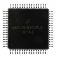
Manufacturer Part Number
MC908MR32CFUE
Description
IC MCU 8MHZ 32K FLASH 64-QFP
Manufacturer
Freescale Semiconductor
Series
HC08r
Datasheet
1.MC908MR16CFUE.pdf
(282 pages)
Specifications of MC908MR32CFUE
Core Processor
HC08
Core Size
8-Bit
Speed
8MHz
Connectivity
SCI, SPI
Peripherals
LVD, POR, PWM
Number Of I /o
44
Program Memory Size
32KB (32K x 8)
Program Memory Type
FLASH
Ram Size
768 x 8
Voltage - Supply (vcc/vdd)
4.5 V ~ 5.5 V
Data Converters
A/D 10x10b
Oscillator Type
Internal
Operating Temperature
-40°C ~ 85°C
Package / Case
64-QFP
Processor Series
HC08MR
Core
HC08
Data Bus Width
8 bit
Data Ram Size
768 B
Interface Type
SCI/SPI
Maximum Clock Frequency
8.2 MHz
Number Of Programmable I/os
44
Number Of Timers
6
Operating Supply Voltage
0 V to 5 V
Maximum Operating Temperature
+ 85 C
Mounting Style
SMD/SMT
Development Tools By Supplier
FSICEBASE, M68CBL05CE
Minimum Operating Temperature
- 40 C
On-chip Adc
10-ch x 10-bit
Lead Free Status / RoHS Status
Lead free / RoHS Compliant
Eeprom Size
-
Lead Free Status / Rohs Status
Lead free / RoHS Compliant
Available stocks
Company
Part Number
Manufacturer
Quantity
Price

Company:
Part Number:
MC908MR32CFUE
Manufacturer:
Freescale Semiconductor
Quantity:
10 000
Part Number:
MC908MR32CFUE
Manufacturer:
NXP/恩智浦
Quantity:
20 000


13.3.3.2 Character Reception
During an SCI reception, the receive shift register shifts characters in from the PTF4/RxD pin. The SCI
data register (SCDR) is the read-only buffer between the internal data bus and the receive shift register.
After a complete character shifts into the receive shift register, the data portion of the character transfers
to the SCDR. The SCI receiver full bit, SCRF, in SCI status register 1 (SCS1) becomes set, indicating that
the received byte can be read. If the SCI receive interrupt enable bit, SCRIE, in SCC2 is also set, the
SCRF bit generates a receiver CPU interrupt request.
13.3.3.3 Data Sampling
The receiver samples the PTF4/RxD pin at the RT clock rate. The RT clock is an internal signal with a
frequency 16 times the baud rate. To adjust for baud rate mismatch, the RT clock is resynchronized at
these times (see
To locate the start bit, data recovery logic does an asynchronous search for a 0 preceded by three 1s.
When the falling edge of a possible start bit occurs, the RT clock begins to count to 16.
To verify the start bit and to detect noise, data recovery logic takes samples at RT3, RT5, and RT7.
Table 13-1
Freescale Semiconductor
•
•
PTF4/RxD
After every start bit
After the receiver detects a data bit change from 1 to 0 (after the majority of data bit samples at
RT8, RT9, and RT10 return a valid 1 and the majority of the next RT8, RT9, and RT10 samples
return a valid 0)
RT CLOCK
RT CLOCK
SAMPLES
CLOCK
RESET
STATE
summarizes the results of the start bit verification samples.
RT
Figure
13-7):
MC68HC908MR32 • MC68HC908MR16 Data Sheet, Rev. 6.1
QUALIFICATION
Figure 13-7. Receiver Data Sampling
START BIT
VERIFICATION
START BIT
START BIT
SAMPLING
DATA
Functional Description
LSB
165
Related parts for MC908MR32CFUE
Image
Part Number
Description
Manufacturer
Datasheet
Request
R

Part Number:
Description:
Manufacturer:
Freescale Semiconductor, Inc
Datasheet:
Part Number:
Description:
Manufacturer:
Freescale Semiconductor, Inc
Datasheet:
Part Number:
Description:
Manufacturer:
Freescale Semiconductor, Inc
Datasheet:
Part Number:
Description:
Manufacturer:
Freescale Semiconductor, Inc
Datasheet:
Part Number:
Description:
Manufacturer:
Freescale Semiconductor, Inc
Datasheet:
Part Number:
Description:
Manufacturer:
Freescale Semiconductor, Inc
Datasheet:
Part Number:
Description:
Manufacturer:
Freescale Semiconductor, Inc
Datasheet:
Part Number:
Description:
Manufacturer:
Freescale Semiconductor, Inc
Datasheet:
Part Number:
Description:
Manufacturer:
Freescale Semiconductor, Inc
Datasheet:
Part Number:
Description:
Manufacturer:
Freescale Semiconductor, Inc
Datasheet:
Part Number:
Description:
Manufacturer:
Freescale Semiconductor, Inc
Datasheet:
Part Number:
Description:
Manufacturer:
Freescale Semiconductor, Inc
Datasheet:
Part Number:
Description:
Manufacturer:
Freescale Semiconductor, Inc
Datasheet:
Part Number:
Description:
Manufacturer:
Freescale Semiconductor, Inc
Datasheet:
Part Number:
Description:
Manufacturer:
Freescale Semiconductor, Inc
Datasheet: