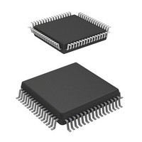
HD6473228F10V Renesas Electronics America, HD6473228F10V Datasheet - Page 77

HD6473228F10V
Manufacturer Part Number
HD6473228F10V
Description
MCU 5V 32K,PB-FREE 64-QFP
Manufacturer
Renesas Electronics America
Series
H8® H8/325r
Datasheet
1.HD6413238F10.pdf
(301 pages)
Specifications of HD6473228F10V
Core Processor
H8/300
Core Size
8-Bit
Speed
10MHz
Connectivity
SCI, UART/USART
Number Of I /o
53
Program Memory Size
8KB (8K x 8)
Program Memory Type
OTP
Ram Size
256 x 8
Voltage - Supply (vcc/vdd)
4.5 V ~ 5.5 V
Oscillator Type
External
Operating Temperature
-20°C ~ 75°C
Package / Case
64-QFP
Lead Free Status / RoHS Status
Lead free / RoHS Compliant
Eeprom Size
-
Data Converters
-
Peripherals
-
Available stocks
Company
Part Number
Manufacturer
Quantity
Price
Company:
Part Number:
HD6473228F10V
Manufacturer:
Renesas Electronics America
Quantity:
10 000
- Current page: 77 of 301
- Download datasheet (2Mb)
Bit i (i = 0 to 2)
IRQiE
Edge-sensed interrupt signals are latched (if enabled) and held until the interrupt is served. They are
latched even if the interrupt mask bit (I) is set in the CCR, and even if bits IRQ
cleared to 0. Level-sensed interrupts are not latched.
4.3.3 External Interrupts
The external interrupts are NMI and IRQ
While the CPU is waiting for one of these interrupts, it is possible to conserve power by entering
software standby mode. When the interrupt arrives, the chip will recover automatically to the
program execution state, handle the interrupt, then continue executing the main program. See
section 12, Power-Down State for further information on software standby mode.
(1) NMI: A nonmaskable interrupt is generated on the rising or falling edge of the NMI input
signal regardless of whether the I (interrupt mask) bit is set in the CCR. The valid edge is selected
by the NMIEG bit in the system control register.
An NMI has highest priority and is always accepted as soon as the current instruction ends, unless
the current instruction is an ANDC, ORC, XORC, or LDC instruction. When an NMI interrupt is
accepted the interrupt mask (I bit) is set, so the NMI handling routine cannot be interrupted except
by another NMI.
The NMI vector number is 3. Its entry is located at address H’0006 in the vector table.
(2) IRQ
of the input, as selected by the ISCR bits. These interrupts can be masked collectively by the I bit in
the CCR, and can be enabled and disabled individually by setting and clearing the bits in the IRQ
enable register. When one of these interrupts is accepted, the I bit is set to 1 to mask further
interrupts (except NMI).
These interrupts are second in priority to NMI. Among them, IRQ
IRQ
input or output pins. When using external interrupts IRQ
bits to 0 to set these pins to the input state.
0
1
2
the lowest priority. Interrupts IRQ
0
to IRQ
2
: These interrupt signals are level-sensed or sensed on the rising or falling edge
Description
IRQi is disabled.
IRQi is enabled.
0
0
to IRQ
to IRQ
2
68
2
do not depend on whether pins IRQ
.
0
to IRQ
2
0
, clear the corresponding DDR
has the highest priority and
(Initial state)
0
E to IRQ
0
to IRQ
2
E are
2
are
Related parts for HD6473228F10V
Image
Part Number
Description
Manufacturer
Datasheet
Request
R

Part Number:
Description:
KIT STARTER FOR M16C/29
Manufacturer:
Renesas Electronics America
Datasheet:

Part Number:
Description:
KIT STARTER FOR R8C/2D
Manufacturer:
Renesas Electronics America
Datasheet:

Part Number:
Description:
R0K33062P STARTER KIT
Manufacturer:
Renesas Electronics America
Datasheet:

Part Number:
Description:
KIT STARTER FOR R8C/23 E8A
Manufacturer:
Renesas Electronics America
Datasheet:

Part Number:
Description:
KIT STARTER FOR R8C/25
Manufacturer:
Renesas Electronics America
Datasheet:

Part Number:
Description:
KIT STARTER H8S2456 SHARPE DSPLY
Manufacturer:
Renesas Electronics America
Datasheet:

Part Number:
Description:
KIT STARTER FOR R8C38C
Manufacturer:
Renesas Electronics America
Datasheet:

Part Number:
Description:
KIT STARTER FOR R8C35C
Manufacturer:
Renesas Electronics America
Datasheet:

Part Number:
Description:
KIT STARTER FOR R8CL3AC+LCD APPS
Manufacturer:
Renesas Electronics America
Datasheet:

Part Number:
Description:
KIT STARTER FOR RX610
Manufacturer:
Renesas Electronics America
Datasheet:

Part Number:
Description:
KIT STARTER FOR R32C/118
Manufacturer:
Renesas Electronics America
Datasheet:

Part Number:
Description:
KIT DEV RSK-R8C/26-29
Manufacturer:
Renesas Electronics America
Datasheet:

Part Number:
Description:
KIT STARTER FOR SH7124
Manufacturer:
Renesas Electronics America
Datasheet:

Part Number:
Description:
KIT STARTER FOR H8SX/1622
Manufacturer:
Renesas Electronics America
Datasheet:

Part Number:
Description:
KIT DEV FOR SH7203
Manufacturer:
Renesas Electronics America
Datasheet:


