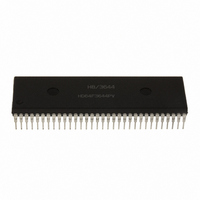
HD6473258P10V Renesas Electronics America, HD6473258P10V Datasheet - Page 165

HD6473258P10V
Manufacturer Part Number
HD6473258P10V
Description
MCU 5V 32K PB-FREE 64-DIP
Manufacturer
Renesas Electronics America
Series
H8® H8/325r
Specifications of HD6473258P10V
Core Size
8-Bit
Program Memory Size
32KB (32K x 8)
Oscillator Type
External
Core Processor
H8/300
Speed
10MHz
Connectivity
SCI, UART/USART
Number Of I /o
53
Program Memory Type
OTP
Ram Size
1K x 8
Voltage - Supply (vcc/vdd)
4.5 V ~ 5.5 V
Operating Temperature
-20°C ~ 75°C
Package / Case
64-DIP
No. Of I/o's
53
Ram Memory Size
1024Byte
Cpu Speed
10MHz
No. Of Timers
3
Digital Ic Case Style
DIP
Supply Voltage
RoHS Compliant
Controller Family/series
H8/330
Rohs Compliant
Yes
Lead Free Status / RoHS Status
Lead free / RoHS Compliant
Eeprom Size
-
Data Converters
-
Peripherals
-
Lead Free Status / RoHS Status
Lead free / RoHS Compliant
Available stocks
Company
Part Number
Manufacturer
Quantity
Price
Company:
Part Number:
HD6473258P10V
Manufacturer:
RENESAS
Quantity:
600
Part Number:
HD6473258P10V
Manufacturer:
HITACHI/日立
Quantity:
20 000
- Current page: 165 of 301
- Download datasheet (2Mb)
Bit 1
OS1
0
0
1
1
8.3 Operation
8.3.1 TCNT Incrementation Timing
The timer counter increments on a pulse generated once for each period of the clock source selected
by bits CKS2 to CKS0 of the TCR.
Internal Clock: Internal clock sources are created from the system clock by a prescaler. The
counter increments on an internal TCNT clock pulse generated from the falling edge of the
prescaler output, as shown in figure 8-2. Bits CKS2 to CKS0 of the TCR can select one of the
three internal clocks (Ø/8, Ø/64, or Ø/1024).
External Clock: If external clock input (TMCI) is selected, the timer counter can increment on the
rising edge, the falling edge, or both edges of the external clock signal. Figure 8-3 shows
incrementation on both edges of the external clock signal.
The external clock pulse width must be at least 1.5 system clock periods for incrementation on a
single edge, and at least 2.5 system clock periods for incrementation on both edges. See figure 8.4.
The counter will not increment correctly if the pulse width is shorter than these values.
Ø
Internal
clock
TCNT clock
pulse
TCNT
Bit 0
OS0
0
1
0
1
N–1
Figure 8-2. Count Timing for Internal Clock Input
Description
No change when compare-match A occurs.
Output changes to 0 when compare-match A occurs.
Output changes to 1 when compare-match A occurs.
Output inverts (toggles) when compare-match A occurs.
N
158
Figure 8-2
(Initial value)
N+1
Related parts for HD6473258P10V
Image
Part Number
Description
Manufacturer
Datasheet
Request
R

Part Number:
Description:
KIT STARTER FOR M16C/29
Manufacturer:
Renesas Electronics America
Datasheet:

Part Number:
Description:
KIT STARTER FOR R8C/2D
Manufacturer:
Renesas Electronics America
Datasheet:

Part Number:
Description:
R0K33062P STARTER KIT
Manufacturer:
Renesas Electronics America
Datasheet:

Part Number:
Description:
KIT STARTER FOR R8C/23 E8A
Manufacturer:
Renesas Electronics America
Datasheet:

Part Number:
Description:
KIT STARTER FOR R8C/25
Manufacturer:
Renesas Electronics America
Datasheet:

Part Number:
Description:
KIT STARTER H8S2456 SHARPE DSPLY
Manufacturer:
Renesas Electronics America
Datasheet:

Part Number:
Description:
KIT STARTER FOR R8C38C
Manufacturer:
Renesas Electronics America
Datasheet:

Part Number:
Description:
KIT STARTER FOR R8C35C
Manufacturer:
Renesas Electronics America
Datasheet:

Part Number:
Description:
KIT STARTER FOR R8CL3AC+LCD APPS
Manufacturer:
Renesas Electronics America
Datasheet:

Part Number:
Description:
KIT STARTER FOR RX610
Manufacturer:
Renesas Electronics America
Datasheet:

Part Number:
Description:
KIT STARTER FOR R32C/118
Manufacturer:
Renesas Electronics America
Datasheet:

Part Number:
Description:
KIT DEV RSK-R8C/26-29
Manufacturer:
Renesas Electronics America
Datasheet:

Part Number:
Description:
KIT STARTER FOR SH7124
Manufacturer:
Renesas Electronics America
Datasheet:

Part Number:
Description:
KIT STARTER FOR H8SX/1622
Manufacturer:
Renesas Electronics America
Datasheet:

Part Number:
Description:
KIT DEV FOR SH7203
Manufacturer:
Renesas Electronics America
Datasheet:


