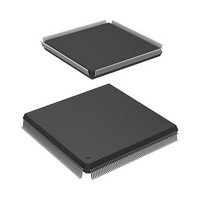
HD6417727F100V Renesas Electronics America, HD6417727F100V Datasheet - Page 456

HD6417727F100V
Manufacturer Part Number
HD6417727F100V
Description
MPU 3V 16K PB-FREE 240-QFP
Manufacturer
Renesas Electronics America
Series
SuperH® SH7700r
Datasheet
1.HD6417727BP100CV.pdf
(1098 pages)
Specifications of HD6417727F100V
Core Processor
SH-3 DSP
Core Size
32-Bit
Speed
100MHz
Connectivity
FIFO, SCI, SIO, SmartCard, USB
Peripherals
DMA, LCD, POR, WDT
Number Of I /o
104
Program Memory Type
ROMless
Ram Size
32K x 8
Voltage - Supply (vcc/vdd)
1.6 V ~ 2.05 V
Data Converters
A/D 6x10b; D/A 2x8b
Oscillator Type
Internal
Operating Temperature
-20°C ~ 75°C
Package / Case
240-QFP
Lead Free Status / RoHS Status
Lead free / RoHS Compliant
Eeprom Size
-
Program Memory Size
-
Available stocks
Company
Part Number
Manufacturer
Quantity
Price
Company:
Part Number:
HD6417727F100V
Manufacturer:
Renesas Electronics America
Quantity:
10 000
- Current page: 456 of 1098
- Download datasheet (7Mb)
Section 14 Direct Memory Access Controller (DMAC)
14.3
When a DMA transfer request is generated, the DMAC starts the transfer according to the
predetermined channel priority order. When a transfer end condition is satisfied, it ends the
transfer. Three types of transfer requests can be, auto request, external request, and on-chip
module request. For the dual address mode, the direct address transfer mode and indirect address
transfer mode are supported. For the bus mode, the burst mode or the cycle steal mode can be
selected.
14.3.1
When transfer conditions have been set to the DMA source address registers (SAR), DMA
destination address registers (DAR), DMA transfer count registers (DMATCR), DMA channel
control registers (CHCR), and DMA operation register (DMAOR), the DMAC transfers data
according to the following procedure:
1. Checks that transfer is enabled (DE = 1, DME = 1, AE = 0, TE = 0, NMIF = 0)
2. When transfer is enabled and a transfer request is generated, the DMAC transfers 1 transfer
3. When the specified number of transfers have been completed (when DMATCR reaches 0), the
4. When an NMI interrupt is generated, the transfer operation is aborted. The transfer operation is
Figure 14.2 shows a flowchart of this procedure.
Rev.6.00 Mar. 27, 2009 Page 398 of 1036
REJ09B0254-0600
unit of data (set with the TS0 and TS1 bits). In auto request mode, the transfer operation begins
automatically when the DE bit and DME bit are set to 1. The DMATCR value will be
decremented on each transfer. The actual transfer flows vary according to the address mode
and bus mode.
transfer operation ends normally. If the IE bit in CHCR is set to 1 at this time, a DEI interrupt
is sent to the CPU.
also aborted when the DE bit in CHCR or the DME bit in DMAOR is changed to 0.
Operation
DMA Transfer Flow
Related parts for HD6417727F100V
Image
Part Number
Description
Manufacturer
Datasheet
Request
R

Part Number:
Description:
KIT STARTER FOR M16C/29
Manufacturer:
Renesas Electronics America
Datasheet:

Part Number:
Description:
KIT STARTER FOR R8C/2D
Manufacturer:
Renesas Electronics America
Datasheet:

Part Number:
Description:
R0K33062P STARTER KIT
Manufacturer:
Renesas Electronics America
Datasheet:

Part Number:
Description:
KIT STARTER FOR R8C/23 E8A
Manufacturer:
Renesas Electronics America
Datasheet:

Part Number:
Description:
KIT STARTER FOR R8C/25
Manufacturer:
Renesas Electronics America
Datasheet:

Part Number:
Description:
KIT STARTER H8S2456 SHARPE DSPLY
Manufacturer:
Renesas Electronics America
Datasheet:

Part Number:
Description:
KIT STARTER FOR R8C38C
Manufacturer:
Renesas Electronics America
Datasheet:

Part Number:
Description:
KIT STARTER FOR R8C35C
Manufacturer:
Renesas Electronics America
Datasheet:

Part Number:
Description:
KIT STARTER FOR R8CL3AC+LCD APPS
Manufacturer:
Renesas Electronics America
Datasheet:

Part Number:
Description:
KIT STARTER FOR RX610
Manufacturer:
Renesas Electronics America
Datasheet:

Part Number:
Description:
KIT STARTER FOR R32C/118
Manufacturer:
Renesas Electronics America
Datasheet:

Part Number:
Description:
KIT DEV RSK-R8C/26-29
Manufacturer:
Renesas Electronics America
Datasheet:

Part Number:
Description:
KIT STARTER FOR SH7124
Manufacturer:
Renesas Electronics America
Datasheet:

Part Number:
Description:
KIT STARTER FOR H8SX/1622
Manufacturer:
Renesas Electronics America
Datasheet:

Part Number:
Description:
KIT DEV FOR SH7203
Manufacturer:
Renesas Electronics America
Datasheet:


