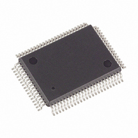
DS5002FMN-16 Maxim Integrated Products, DS5002FMN-16 Datasheet - Page 19

DS5002FMN-16
Manufacturer Part Number
DS5002FMN-16
Description
IC MPU SECURE 16MHZ IND 80-TQFP
Manufacturer
Maxim Integrated Products
Series
DS500xr
Datasheet
1.DS5002FPM-16.pdf
(25 pages)
Specifications of DS5002FMN-16
Core Processor
8051
Core Size
8-Bit
Speed
16MHz
Connectivity
EBI/EMI, SIO, UART/USART
Peripherals
Power-Fail Reset, WDT
Number Of I /o
32
Program Memory Type
SRAM
Ram Size
128 x 8
Voltage - Supply (vcc/vdd)
4.5 V ~ 5.5 V
Oscillator Type
External
Operating Temperature
-40°C ~ 85°C
Package / Case
80-MQFP, 80-PQFP
Processor Series
DS5002
Core
8051
Data Bus Width
8 bit
Program Memory Size
32 KB, 64 KB, 128 KB
Data Ram Size
32 KB, 64 KB, 128 KB
Interface Type
UART
Maximum Clock Frequency
16 MHz
Number Of Programmable I/os
32
Number Of Timers
2
Operating Supply Voltage
4.5 V to 5.5 V
Maximum Operating Temperature
+ 85 C
Mounting Style
SMD/SMT
3rd Party Development Tools
PK51, CA51, A51, ULINK2
Minimum Operating Temperature
- 40 C
Lead Free Status / RoHS Status
Contains lead / RoHS non-compliant
Eeprom Size
-
Program Memory Size
-
Data Converters
-
Available stocks
Company
Part Number
Manufacturer
Quantity
Price
Company:
Part Number:
DS5002FMN-16
Manufacturer:
Maxim Integrated
Quantity:
10 000
Company:
Part Number:
DS5002FMN-16+
Manufacturer:
Maxim Integrated Products
Quantity:
135
Company:
Part Number:
DS5002FMN-16+
Manufacturer:
Maxim Integrated
Quantity:
10 000
Table 1. Serial Bootstrap Loader Commands
Execution of certain bootstrap loader commands result in the loading of the newly generated 64-bit random number
into the encryption key word. These commands are as follows:
Fill
Load
Dump D
Verify V
CRC
Execution of the Fill and Load commands result in the data loaded into the NV RAM in an encrypted form
determined by the value of the newly generated key word. The subsequent execution of the Dump command within
the same bootstrap session causes the contents of the encrypted RAM to be read out and transmitted back to the
host PC in decrypted form. Similarly, execution of the Verify command within the same bootstrap session causes
the incoming absolute hex data to be compared against the true contents of the encrypted RAM, and the CRC
command returns the CRC value calculated from the true contents of the encrypted RAM. As long as any of the
above commands are executed within the same bootstrap session, the loaded key value remains the same, and
the contents of the encrypted program/data NV RAM can be read or written normally and freely until the security
lock bit is set.
When the security lock bit is set using the Z command, no further access to the true RAM contents is possible
using any bootstrap command or by any other means.
INSTRUCTION SET
The DS5002FP executes an instruction set that is object code-compatible with the industry standard 8051
microcontroller. As a result, software development packages such as assemblers and compilers that have been
written for the 8051 are compatible with the DS5002FP. A complete description of the instruction set and operation
are provided in the Secure Microcontroller User’s Guide.
Also note that the DS5002FP is embodied in the DS2252T module. The DS2252T combines the DS5002FP with
between 32k and 128k of SRAM, a lithium cell, and a real-time clock. This is packaged in a 40-pin SIMM module.
MEMORY ORGANIZATION
Figure 10
potentially available to the byte-wide bus. This preserves the I/O ports for application use. The user controls the
portion of memory that is actually mapped to the byte-wide bus by selecting the program range and data range.
Any area not mapped into the NV RAM is reached by the expanded bus on ports 0 and 2. An alternate
configuration allows dynamic partitioning of a 64k space as shown in
another 64k of potential data storage or memory mapped peripheral space as shown in
COMMAND
W
M
C
D
G
N
P
R
U
V
F
L
T
Z
I
F
L
C
illustrates the memory map accessed by the DS5002FP. The entire 64k of program and 64k of data are
Return CRC-16 of the program/data NV RAM
Dump Intel Hex file
Fill program/data NV RAM
Get data from P1, P2, and P3
N/A on the DS5002FP
Load Intel Hex file
Toggle modem available bit
Set freshness seal—all program and data is lost
Put data into P0, P1, P2, and P3
Read status of NV SFRs (MCON, RPCTL, MSL, CALIB)
Trace (echo) incoming Intel Hex code
Clear Security Lock
Verify program/data NV RAM with incoming Intel Hex data
Write special function registers (MCON, RPCTL, MSL, CALIB)
Set security lock
FUNCTION
19 of 25
Figure
11. Selecting PES = 1 provides
Figure
12. These


