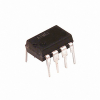
ATTINY12V-1PC Atmel, ATTINY12V-1PC Datasheet - Page 74

ATTINY12V-1PC
Manufacturer Part Number
ATTINY12V-1PC
Description
IC AVR MCU 1MHZ 1.8V 8DIP
Manufacturer
Atmel
Series
AVR® ATtinyr
Specifications of ATTINY12V-1PC
Core Processor
AVR
Core Size
8-Bit
Speed
1.2MHz
Peripherals
POR, WDT
Number Of I /o
6
Program Memory Size
1KB (512 x 16)
Program Memory Type
FLASH
Eeprom Size
64 x 8
Voltage - Supply (vcc/vdd)
1.8 V ~ 5.5 V
Oscillator Type
Internal
Operating Temperature
0°C ~ 70°C
Package / Case
8-DIP (0.300", 7.62mm)
Data Bus Width
8 bit
Maximum Clock Frequency
8 MHz
Number Of Programmable I/os
6
Number Of Timers
1
Operating Supply Voltage
1.8 V to 5.5 V
Maximum Operating Temperature
+ 85 C
Mounting Style
Through Hole
Minimum Operating Temperature
- 55 C
Lead Free Status / RoHS Status
Contains lead / RoHS non-compliant
Ram Size
-
Data Converters
-
Connectivity
-
Lead Free Status / Rohs Status
No
Other names
ATTINY12V1PC
ATtiny12 Typical
Characteristics
74
ATtiny11/12
The following charts show typical behavior. These data are characterized, but not
tested. All current consumption measurements are performed with all I/O pins config-
ured as inputs and with internal pull-ups enabled. A sine wave generator with rail-to-rail
output is used as clock source.
The power consumption in Power-down Mode is independent of clock selection.
The current consumption is a function of several factors such as: operating voltage,
operating frequency, loading of I/O pins, switching rate of I/O pins, code executed and
ambient temperature. The dominating factors are operating voltage and frequency.
The current drawn from capacitive loaded pins may be estimated (for one pin) as
C
ing frequency of I/O pin.
The parts are characterized at frequencies higher than test limits. Parts are not guaran-
teed to function properly at frequencies higher than the ordering code indicates.
The difference between current consumption in Power-down Mode with Watchdog
Timer enabled and Power-down Mode with Watchdog Timer disabled represents the dif-
ferential current drawn by the Watchdog timer.
Figure 56. Active Supply Current vs. V
L
*
V
CC
*f where C
1.8
1.6
1.4
1.2
0.8
0.6
0.4
0.2
1
0
1.5
2
L
= load capacitance, V
2.5
DEVICE CLOCKED BY 1.2MHz INTERNAL RC OSCILLATOR
ACTIVE SUPPLY CURRENT vs. V
3
3.5
CC
CC
, Device Clocked by Internal Oscillator
V
cc
= operating voltage and f = average switch-
(V)
4
4.5
cc
5
T = 25
T = 85
A
A
˚
˚
C
C
5.5
1006F–AVR–06/07
6


