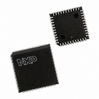
P87C51RC+4A,512 NXP Semiconductors, P87C51RC+4A,512 Datasheet - Page 14

P87C51RC+4A,512
Manufacturer Part Number
P87C51RC+4A,512
Description
IC 80C51 MCU 512 RAM 44PLCC
Manufacturer
NXP Semiconductors
Series
87Cr
Datasheet
1.P87C51RC2FA512.pdf
(67 pages)
Specifications of P87C51RC+4A,512
Core Processor
8051
Core Size
8-Bit
Speed
16MHz
Connectivity
EBI/EMI, UART/USART
Peripherals
POR, PWM, WDT
Number Of I /o
32
Program Memory Size
32KB (32K x 8)
Program Memory Type
OTP
Ram Size
512 x 8
Voltage - Supply (vcc/vdd)
2.7 V ~ 5.5 V
Oscillator Type
Internal
Operating Temperature
0°C ~ 70°C
Package / Case
44-PLCC
For Use With
OM10064 - EMULATOR 80C51 PDS51-MK2
Lead Free Status / RoHS Status
Lead free / RoHS Compliant
Eeprom Size
-
Data Converters
-
Other names
935252130512
P87C51RC+4A
P87C51RC+4A
P87C51RC+4A
P87C51RC+4A
Philips Semiconductors
2003 Jan 24
80C51 8-bit microcontroller family
with 512B/1KB RAM, low voltage (2.7 to 5.5 V), low power, high
speed (30/33 MHz)
TCON
*d = 6 in 6-clock mode; d = 12 in 12-clock mode.
Timer n
Gate bit
INTn Pin
BIT
TCON.7
TCON.6
TCON.5
TCON.4
TCON.3
TCON.2
TCON.1
TCON.0
OSC
Address = 88H
Bit Addressable
Tn Pin
SYMBOL
TF1
TR1
TF0
TR0
IE1
IT1
IE0
IT0
TRn
d*
TF1
FUNCTION
Timer 1 overflow flag. Set by hardware on Timer/Counter overflow.
Cleared by hardware when processor vectors to interrupt routine, or clearing the bit in software.
Timer 1 Run control bit. Set/cleared by software to turn Timer/Counter on/off.
Timer 0 overflow flag. Set by hardware on Timer/Counter overflow.
Cleared by hardware when processor vectors to interrupt routine, or by clearing the bit in software.
Timer 0 Run control bit. Set/cleared by software to turn Timer/Counter on/off.
Interrupt 1 Edge flag. Set by hardware when external interrupt edge detected.
Cleared when interrupt processed.
Interrupt 1 type control bit. Set/cleared by software to specify falling edge/low level triggered
external interrupts.
Interrupt 0 Edge flag. Set by hardware when external interrupt edge detected.
Cleared when interrupt processed.
Interrupt 0 Type control bit. Set/cleared by software to specify falling edge/low level
triggered external interrupts.
7
Figure 3. Timer/Counter 0/1 Mode 0: 13-Bit Timer/Counter
Figure 4. Timer/Counter 0/1 Control (TCON) Register
TR1
8KB/16KB/32KB/64KB OTP
6
C/T = 0
C/T = 1
TF0
5
TR0
4
Control
14
IE1
3
IT1
2
(5 Bits)
TLn
P87C51RA2/RB2/RC2/RD2
IE0
1
(8 Bits)
THn
IT0
0
Reset Value = 00H
TFn
SU01618
Interrupt
SU01516
Product data


