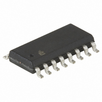
X40235S16I-AT1 Intersil, X40235S16I-AT1 Datasheet - Page 31

X40235S16I-AT1
Manufacturer Part Number
X40235S16I-AT1
Description
IC VOLTAGE MON TRPL EE 16-SOIC
Manufacturer
Intersil
Type
Multi-Voltage Supervisorr
Datasheet
1.X40231S16I-A.pdf
(36 pages)
Specifications of X40235S16I-AT1
Number Of Voltages Monitored
3
Output
Open Drain, Open Drain
Reset
Active High/Active Low
Reset Timeout
Adjustable/Selectable
Voltage - Threshold
1.75V, 2.2V, 2.95V
Operating Temperature
-40°C ~ 85°C
Mounting Type
Surface Mount
Package / Case
16-SOIC (0.300", 7.5mm Width)
Lead Free Status / RoHS Status
Contains lead / RoHS non-compliant
POTENTIOMETER CHARACTERISTICS
Notes: 1. Power Rating between the wiper terminal R WX(n) and the end terminals R HX V
Notes: 2. Absolute Linearity is utilized to determine actual wiper resistance versus, expected resistance = (R wx(n) (actual) - R wx(n) (expected)) = ±1
Notes: 3. Relative Linearity is a measure of the error in step size between taps = R Wx(n+1) - [R wx(n) + Ml] = ±0.2 Ml (x = 0,1,2)
Notes: 4. 1 Ml = Minimum Increment = R TOT / (Number of taps in DCP - 1).
Notes: 5. Typical values are for T
Notes: 6. This parameter is periodically sampled and not 100% tested.
Symbol
R
V
V
P
R
I
C
C
t
W
wr
RHx
RLx
R
TOL
W
H
W
/C
L
/
Ml Maximum (x = 0,1,2).
End to End Resistance Tolerance
R
R
Power Rating
DCP Wiper Resistance
Wiper Current
Noise
Absolute Linearity
Relative Linearity
R
Ratiometric Temperature
Coefficient
Potentiometer Capacitances
Wiper Response time
H
L
TOTAL
Terminal Voltage (x = 0,1,2)
Terminal Voltage (x = 0,1,2)
Temperature Coefficient
Parameter
(1)
31
A
= 25°C and nominal supply voltage.
(3)
(2)
X40231, X40233, X40235, X40237, X40239
Min.
VSS
VSS
-20
-1
-1
10/10/25
±300
±300
Typ.
200
400
Limits
Max.
1200
V
VSS
+20
400
±30
200
4.4
10
+1
+1
CC
5
SS
- for ANY tap position n, (x = 0,1,2).
ppm/°C
ppm/°C
ppm/°C
Units
√(Hz)
√(Hz)
MI
MI
mW
mW
mA
mV
mV
pF
µs
%
Ω
Ω
V
V
(4)
(4)
In a ratiometric circuit, R
divides out of the equation and
accuracy is determined by XDCP
resolution.
R
R
R
V
V
I
V
V
I
R
R
R
R
R
R
(Voltage divider configuration)
See Figure 26.
See Figure 34.
W
W
CC
RLx
CC
RLx
L
TOTAL
TOTAL
TOTAL
TOTAL
w(n)(actual)
w(n+1)
TOTAL
TOTAL
= 50 uA /500 uA (100/10kΩ).
= 27 uA /270 uA (100/10 kΩ).
Terminal internally tied to gnd.
Test Conditions/Notes
= 5 V, V
= 2.7 V, V
= VSS (x = 0,1,2),
= VSS (x = 0,1,2),
- [R
= 10kΩ (DCP0, DCP1)
= 100kΩ (DCP2)
= 10kΩ (DCP0, DCP1)
= 100kΩ (DCP2)
= 10kΩ (DCP0, DCP1)
= 100kΩ (DCP2)
w(n) + MI
- R
RHx
w(n)(expected)
RHx
= V
= V
]
CC
CC
,
TOTAL
,
April 11, 2005
FN8115.0


