LM150K STMicroelectronics, LM150K Datasheet - Page 9
LM150K
Manufacturer Part Number
LM150K
Description
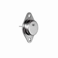
IC VOLT REG 3A ADJ 3-TERM TO-3
Manufacturer
STMicroelectronics
Datasheet
1.LM350K.pdf
(14 pages)
Specifications of LM150K
Regulator Topology
Positive Adjustable
Voltage - Output
1.2 ~ 25 V
Number Of Regulators
1
Current - Output
3A
Current - Limit (min)
3A
Operating Temperature
-55°C ~ 150°C
Mounting Type
Through Hole
Package / Case
TO-204, TO-3
Polarity
Positive
Number Of Outputs
1
Output Type
Adjustable
Output Voltage
1.2 V to 25 V
Output Current
1.5 A
Line Regulation
0.005 % / V
Load Regulation
0.1 %
Input Voltage Max
35 V
Maximum Operating Temperature
+ 150 C
Minimum Operating Temperature
- 55 C
Maximum Power Dissipation
30000 mW
Mounting Style
Through Hole
Reference Voltage
1.29 V
Lead Free Status / RoHS Status
Lead free / RoHS Compliant
Voltage - Input
-
Voltage - Dropout (typical)
-
Lead Free Status / Rohs Status
Lead free / RoHS Compliant
Available stocks
Company
Part Number
Manufacturer
Quantity
Price


6.2
6.3
decrease in capacitance at frequencies around 0.5 MHz. For this reason, 0.01 µF disc may
seem to work better than a 0.1 µF disc as a bypass.
Although the LM350 is stable with no output capacitors, like any feedback circuit, certain
values of external capacitance can cause excessive ringing. This occurs with values
between 500 pF and 5000 pF. A 1 µF solid tantalum (or 25 µF aluminium electrolytic) on the
output swamps this effect and insures stability.
Load regulation
The LM350 is capable of providing extremely good load regulation but a few precautions are
needed to obtain maximum performance. The current set resistor connected between the
adjustment terminal and the output terminal (usually 240 Ω) should be tied directly to the
output of the regulator rather than near the load. This eliminates line drops from appearing
effectively in series with the reference and degrading regulation. For example, a 15 V
regulator with 0.05 Ω resistance between the regulator and load will have a load regulation
due to line resistance of 0.05 Ω x I
effective line resistance will be 0.05 Ω (1 + R
Figure 5
the TO-3 package, it is easy to minimize the resistance from the case to the set resistor, by
using 2 separate leads to the case. The ground of R
load to provide remote ground sensing and improve load regulation.
Protection diodes
When external capacitors are used with any IC regulator it is sometimes necessary to add
protection diodes to prevent the capacitors from discharging through low current points into
the regulator. Most 20 µF capacitors have low enough internal series resistance to deliver
20 A spikes when shorted. Although the surge is short, there is enough energy to damage
parts of the IC.
When an output capacitor is connected to a regulator and the input is shorted, the output
capacitor will discharge into the output of the regulator. The discharge current depends on
the value of the capacitor, the output voltage of the regulator, and the rate of decrease of V
In the LM350 this discharge path is through a large junction that is able to sustain 25 A
surge with no problem. This is not true of other types of positive regulators. For output
capacitors of 100 µF or less at output of 15 V or less, there is no need to use diodes.
The bypass capacitor on the adjustment terminal can discharge through a low current
junction. Discharge occurs when either the input or output is shorted. Internal to the LM350
is a 50 Ω resistor which limits the peak discharge current. No protection is needed for output
voltages of 25 V or less and 10 µF capacitance.
diodes included for use with outputs greater than 25 V and high values of output
capacitance.
shows the effect of resistance between the regulator and 140 Ω set resistor. With
L
. If the set resistor is connected near the load the
2
/R
1
Figure 6
) or in this case, 11.5 times worse.
2
can be returned near the ground of the
shows an LM350 with protection
9/14
I
.
Related parts for LM150K
Image
Part Number
Description
Manufacturer
Datasheet
Request
R

Part Number:
Description:
STMicroelectronics [RIPPLE-CARRY BINARY COUNTER/DIVIDERS]
Manufacturer:
STMicroelectronics
Datasheet:
Part Number:
Description:
STMicroelectronics [LIQUID-CRYSTAL DISPLAY DRIVERS]
Manufacturer:
STMicroelectronics
Datasheet:

Part Number:
Description:
BOARD EVAL FOR MEMS SENSORS
Manufacturer:
STMicroelectronics
Datasheet:
Part Number:
Description:
NPN TRANSISTOR POWER MODULE
Manufacturer:
STMicroelectronics
Datasheet:
Part Number:
Description:
TURBOSWITCH ULTRA-FAST HIGH VOLTAGE DIODE
Manufacturer:
STMicroelectronics
Datasheet:
Part Number:
Description:
Manufacturer:
STMicroelectronics
Datasheet:
Part Number:
Description:
DIODE / SCR MODULE
Manufacturer:
STMicroelectronics
Datasheet:
Part Number:
Description:
DIODE / SCR MODULE
Manufacturer:
STMicroelectronics
Datasheet:
Part Number:
Description:
Search -----> STE16N100
Manufacturer:
STMicroelectronics
Datasheet:
Part Number:
Description:
Search ---> STE53NA50
Manufacturer:
STMicroelectronics
Datasheet:
Part Number:
Description:
NPN Transistor Power Module
Manufacturer:
STMicroelectronics
Datasheet:
Part Number:
Description:
DIODE / SCR MODULE
Manufacturer:
STMicroelectronics
Datasheet: