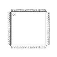
XR16L784IV-F Exar Corporation, XR16L784IV-F Datasheet - Page 21

XR16L784IV-F
Manufacturer Part Number
XR16L784IV-F
Description
IC UART 8B 3.3V QUAD 64LQFP
Manufacturer
Exar Corporation
Type
IrDA or RS- 485r
Datasheet
1.XR16L784CV-F.pdf
(51 pages)
Specifications of XR16L784IV-F
Number Of Channels
4, QUART
Package / Case
64-LQFP
Features
*
Fifo's
64 Byte
Protocol
RS485
Voltage - Supply
2.97 V ~ 5.5 V
With Auto Flow Control
Yes
With Irda Encoder/decoder
Yes
With False Start Bit Detection
Yes
With Modem Control
Yes
Mounting Type
Surface Mount
Data Rate
6.25 Mbps
Supply Voltage (max)
5.5 V
Supply Voltage (min)
2.97 V
Supply Current
5 mA
Maximum Operating Temperature
+ 85 C
Minimum Operating Temperature
- 40 C
Mounting Style
SMD/SMT
Operating Supply Voltage
3.3 V or 5 V
No. Of Channels
4
Uart Features
Tx/Rx FIFO Counters
Supply Voltage Range
2.97V To 5.5V
Operating Temperature Range
-40°C To +85°C
Digital Ic Case Style
LQFP
Rohs Compliant
Yes
Lead Free Status / RoHS Status
Lead free / RoHS Compliant
Lead Free Status / RoHS Status
Lead free / RoHS Compliant, Lead free / RoHS Compliant
Other names
1016-1282
Available stocks
Company
Part Number
Manufacturer
Quantity
Price
Company:
Part Number:
XR16L784IV-F
Manufacturer:
Exar Corporation
Quantity:
10 000
Part Number:
XR16L784IV-F
Manufacturer:
EXAR/艾科嘉
Quantity:
20 000
REV. 1.2.3
The XR16L784 has a global interrupt source register set that consists of 4 consecutive registers [INT0, INT1,
INT2 and INT3]. Register INT3 is not used in the 784 UART, only in the 8-channel XR16L788. The 3 registers
are in the device configuration register address space.
All 4 registers default to logic zero (as indicated in square braces) for no interrupt pending. All 4 channel
interrupts are enabled or disabled in each channel’s IER register. INT0 shows individual status for each
channel while INT1 and INT2 show the details of the source of each channel’s interrupt with its unique 3-bit
encoding.
up interrupts are masked in the device configuration registers,
generated by the 784 when awakened from sleep if all 4 channels were placed in the sleep mode previously.
Reading INT0 will clear this wake-up interrupt.
Each bit in the INT0 register gives an indication of the channel that has requested service.
For example, bit-0 represents channel 0 and bit-3 indicates channel 3. Bits 4 to 7 are reserved and remains at
logic zero. Logic one indicates the channel N [3:0] has called for service. The interrupt bit clears after reading
the appropiate register of the interrupting UART channel register (ISR, LSR and MSR).
interrupt clearing details.
INT2 and INT1 provide a 12-bit (3 bits per channel) encoded interrupt indicator.
encoding and their priority order. The 16-bit Timer time-out interrupt will show up only as a channel 0 interrupt .
For other channels, interrupt 7 is reserved.
.
F
3.1.1
3.1.1.1
3.1.1.2
IGURE
Bit
2
Reserved
14. T
Bit
1
Figure 14
The Global Interrupt Source Registers
Bit
0
HE
INT0 Channel Interrupt Indicator:
INT1 and INT2 Interrupt Source Locator
INT3 Register
Bit
G
2
Reserved
LOBAL
Bit
1
shows the 4 interrupt registers in sequence for clarity. The 16-bit timer and sleep wake-
Bit
0
I
NTERRUPT
Bit
2
INT3 (Rsvd)
Reserved
Rsvd Rsvd Rsvd Rsvd
Bit-7
[0x00]
Bit
1
R
Bit
Bit-6
0
Individual UART Channel Interrupt Status
EGISTERS
Bit
2
Reserved
Bit-5
INT0, INT1, INT2 and INT3
Bit
[0x00]
1
INT2
, INT0, INT1, INT2
Interrupt Registers,
INT2 Register
INT0 Register
Bit
Bit-4
0
Bit
21
2
HIGH PERFORMANCE 2.97V TO 5.5V QUAD UART
Channel-3
Ch-3
Bit-3
Bit
1
[0x00]
INT1
Bit-2
Ch-2
Bit
0
Bit
AND
2
Channel-2
Ch-1
TIMERCNTL and SLEEP.
Bit-1
Rsvd
Bit-7
Bit
1
INT3
[0x00]
INT0
Rsvd
Bit-6
Ch-0
Bit-0
Bit
0
Rsvd
Bit-5
Bit
2
Channel-1
INT0 Register
Rsvd
Bit-4
INT1 Register
Bit
1
Table 9
Ch-3
Bit-3
Bit
0
Ch-2 Ch-1 Ch-0
Bit-2
Bit
2
See Table 13
Channel-0
An interrupt
shows the 3 bit
Bit-1
Bit
XR16L784
1
Bit-0
Bit
0
for
is


