XR16L784IV-F Exar Corporation, XR16L784IV-F Datasheet - Page 5
XR16L784IV-F
Manufacturer Part Number
XR16L784IV-F
Description
IC UART 8B 3.3V QUAD 64LQFP
Manufacturer
Exar Corporation
Type
IrDA or RS- 485r
Datasheet
1.XR16L784CV-F.pdf
(51 pages)
Specifications of XR16L784IV-F
Number Of Channels
4, QUART
Package / Case
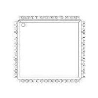
64-LQFP
Features
*
Fifo's
64 Byte
Protocol
RS485
Voltage - Supply
2.97 V ~ 5.5 V
With Auto Flow Control
Yes
With Irda Encoder/decoder
Yes
With False Start Bit Detection
Yes
With Modem Control
Yes
Mounting Type
Surface Mount
Data Rate
6.25 Mbps
Supply Voltage (max)
5.5 V
Supply Voltage (min)
2.97 V
Supply Current
5 mA
Maximum Operating Temperature
+ 85 C
Minimum Operating Temperature
- 40 C
Mounting Style
SMD/SMT
Operating Supply Voltage
3.3 V or 5 V
No. Of Channels
4
Uart Features
Tx/Rx FIFO Counters
Supply Voltage Range
2.97V To 5.5V
Operating Temperature Range
-40°C To +85°C
Digital Ic Case Style
LQFP
Rohs Compliant
Yes
Lead Free Status / RoHS Status
Lead free / RoHS Compliant
Lead Free Status / RoHS Status
Lead free / RoHS Compliant, Lead free / RoHS Compliant
Other names
1016-1282
Available stocks
Company
Part Number
Manufacturer
Quantity
Price
Company:

Part Number:
XR16L784IV-F
Manufacturer:
Exar Corporation
Quantity:
10 000
Part Number:
XR16L784IV-F
Manufacturer:
EXAR/艾科嘉
Quantity:
20 000


REV. 1.2.3
Pin Descriptions
N
ANCILLARY SIGNALS
OTE
TMRCK
CTS3#
DTR3#
DSR3#
RTS3#
XTAL1
XTAL2
16/68#
: Pin type: I=Input, O=Output, IO= Input/output, OD=Output Open Drain.
CD3#
RST#
N
ENIR
GND
RI3#
VCC
RX3
TX3
AME
10,29,51
9,30,52
P
28
21
26
22
27
23
24
25
50
49
31
32
20
19
IN
#
T
YPE
O
O
O
O
I
I
I
I
I
I
I
I
I
I
UART channel 3 Transmit Data or infrared transmit data. Normal TXD output
idles HIGH while infrared TXD output idles LOW.
UART channel 3 Receive Data or infrared receive data. Normal RXD input
idles HIGH while infrared RXD input idles LOW. In the infrared mode, the
polarity of the incoming RXD signal can be selected via FCTR bit-4. If this bit
is a logic 0, a LOW on the RXD input is considered a mark and if this bit is a
logic 1, a HIGH on the RXD input is considered a space.
UART channel 3 Request to Send or general purpose output (active low).
See description of RTS0# pin.
UART channel 3 Clear to Send or general purpose input (active low).d. See
description of CTS0# pin.
UART channel 3 Data Terminal Ready or general purpose output (active low).
See description of DTS0# pin.
UART channel 3 Data Set Ready or general purpose input (active low). See
description of DSR0# pin.
UART channel 3 Carrier Detect or general purpose input (active low).
UART channel 3 Ring Indicator or general purpose input (active low).
Crystal or external clock input. Caution: this input is not 5V tolerant.
Crystal or buffered clock output.
16-bit timer/counter external clock input.
Infrared mode enable (active high). This pin is sampled during power up, fol-
lowing a hardware reset (RST#) or soft-reset (register RESET). It can be
used to start up all 8 UARTs in the infrared mode. The sampled logic state is
transferred to MCR bit-6 in the UART.
Reset (active low). The configuration and UART registers are reset to default
values, see Table-15.
Intel or Motorola data bus interface select. HIGH selects Intel bus interface
and LOW selects Motorola interface. This input affects the functionality of
IOR#, IOW# and CS# pins.
+5V or +3.3V supply, all inputs are 5V tolerant except for XTAL1.
Power supply common, ground.
5
HIGH PERFORMANCE 2.97V TO 5.5V QUAD UART
D
ESCRIPTION
XR16L784
Related parts for XR16L784IV-F
Image
Part Number
Description
Manufacturer
Datasheet
Request
R

Part Number:
Description:
High Performance 5V And 3.3V Quad Uart
Manufacturer:
Exar Corporation
Datasheet:
Part Number:
Description:
BiCMOS Fixed, Quad, Voltage Output, Single or Dual Supply 8-Bit Digital-to-Analog Converter
Manufacturer:
Exar Corporation
Datasheet:
Part Number:
Description:
Manufacturer:
Exar Corporation
Datasheet:
Part Number:
Description:
Voltage-Controlled Oscillator
Manufacturer:
Exar Corporation
Datasheet:
Part Number:
Description:
INTEGRATED LINE TRANSMITTER
Manufacturer:
Exar Corporation
Datasheet:
Part Number:
Description:
Monolithic Function Generator
Manufacturer:
Exar Corporation
Datasheet:
Part Number:
Description:
CMOS Microprocessor Compatible Double-Buffered 12-Bit Digital-to-Analog Converter
Manufacturer:
Exar Corporation
Datasheet:
Part Number:
Description:
CMOS 6 BIT HIGH SPEED ANALOG TO DIGITAL CONVERTER
Manufacturer:
Exar Corporation
Datasheet:
Part Number:
Description:
Manufacturer:
Exar Corporation
Datasheet:
Part Number:
Description:
Manufacturer:
Exar Corporation
Datasheet:
Part Number:
Description:
8-Channel, Voltage Output 10 MHz Input Bandwidth 8-Bit Multiplying DACs with Serial Digital Data Por
Manufacturer:
Exar Corporation
Datasheet:
Part Number:
Description:
15 V CMOS Multiplying10-Bit Digital-to-Analog Converter
Manufacturer:
Exar Corporation
Datasheet:
Part Number:
Description:
Monolithic Function Generator
Manufacturer:
Exar Corporation
Datasheet: