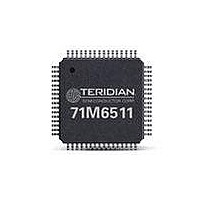
71M6511-IGT/F Maxim Integrated Products, 71M6511-IGT/F Datasheet - Page 50

71M6511-IGT/F
Manufacturer Part Number
71M6511-IGT/F
Description
IC ENERGY METER RESIDENT 64-LQFP
Manufacturer
Maxim Integrated Products
Datasheet
1.71M6511H-IGTF.pdf
(98 pages)
Specifications of 71M6511-IGT/F
Lead Free Status / RoHS Status
Lead free / RoHS Compliant
Available stocks
Company
Part Number
Manufacturer
Quantity
Price
Company:
Part Number:
71M6511-IGT/F
Manufacturer:
ST
Quantity:
1 500
Company:
Part Number:
71M6511-IGT/F
Manufacturer:
Maxim Integrated
Quantity:
10 000
Data Flow
The data flow between CE and MPU is shown in Figure 17. In a typical application, the 32-bit compute engine (CE)
sequentially processes the samples from the voltage inputs on pins IA, VA, and IB, performing calculations to measure active
power (Wh), reactive power (VARh), A
MPU, processed further and output using the peripheral devices available to the MPU.
CE/MPU Communication
Figure 18 shows the functional relationship between CE and MPU. The CE is controlled by the MPU via shared registers in the
I/O RAM and by registers in the CE DRAM. The CE outputs two interrupt signals to the MPU: CE_BUSY and XFER_BUSY,
which are connected to the MPU interrupt service inputs as external interrupts. CE_BUSY indicates that the CE is actively
processing data. This signal will occur once every multiplexer cycle. XFER_BUSY indicates that the CE is updating data to the
output region of the CE RAM. This will occur whenever the CE has finished generating a sum by completing an accumulation
interval determined by SUM_CYCLES * PRE_SAMPS samples. Interrupts to the MPU occur on the falling edges of the
XFER_BUSY and CE_BUSY signals.
Figure 19 shows the sequence of events between CE and MPU upon reset or power-up. In a typical application, the sequence
of events is as follows:
It is important to note that the length of the accumulation interval, as determined by N
PRE_SAMPS is not an exact multiple of 1000ms. For example, if SUM_CYCLES = 60, and PRE_SAMPS = 00 (42), the resulting
accumulation interval is:
This means that accurate time measurements should be based on the RTC, not the accumulation interval.
Page: 50 of 98
1)
2)
3)
4)
5)
A Maxim Integrated Products Brand
Upon power-up, the MPU initializes the hardware, including disabling the CE
The MPU loads the code for the CE into the CE PRAM
The MPU loads CE data into the CE DRAM.
The MPU starts the CE by setting the CE_EN bit in the I/O RAM.
The CE then repetitively executes its code, generating results and storing them in the CE DRAM
Samples
τ
=
2
© 2005–2010 Teridian Semiconductor Corporation
h, and V
Pulses
Processor
N
CE
f
I/O RAM (Configuration RAM)
ACC
Pre-
S
=
Figure 17: MPU/CE Data Flow
2
h for four-quadrant metering. These measurements are then accessed by the
32768
60
13
⋅
IRQ
Data
42
Hz
=
2520
Single-Phase Energy Meter IC
Processor
2520
MPU
Post-
.
62
Hz
71M6511/71M6511H
=
999
DATA SHEET
.
75
ms
Processed
ACC
Metering
, the product of SUM_CYCLES and
Data
NOVEMBER 2010
V2.7


