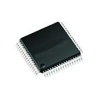
71M6511H-IGT/F Maxim Integrated Products, 71M6511H-IGT/F Datasheet - Page 54

71M6511H-IGT/F
Manufacturer Part Number
71M6511H-IGT/F
Description
IC ENERGY METER RESIDENT 64-LQFP
Manufacturer
Maxim Integrated Products
Datasheet
1.71M6511H-IGTF.pdf
(98 pages)
Specifications of 71M6511H-IGT/F
Processor Series
6511x
Core
80515
Data Bus Width
8 bit
Program Memory Type
Flash
Program Memory Size
64 KB
Data Ram Size
7 KB
Interface Type
I2C, SSI, UART
Maximum Clock Frequency
5 MHz
Number Of Programmable I/os
12
Number Of Timers
2
Operating Supply Voltage
3 V to 3.6 V
Maximum Operating Temperature
+ 85 C
Mounting Style
SMD/SMT
Package / Case
LQFP-64
3rd Party Development Tools
PK51, CA51, A51, ULINK2
Development Tools By Supplier
71M6511H-DB
Minimum Operating Temperature
- 40 C
On-chip Adc
22 bit Delta Sigma
Lead Free Status / RoHS Status
Lead free / RoHS Compliant
Available stocks
Company
Part Number
Manufacturer
Quantity
Price
Company:
Part Number:
71M6511H-IGT/F
Manufacturer:
PERICOM
Quantity:
1 200
Company:
Part Number:
71M6511H-IGT/F
Manufacturer:
Maxim Integrated
Quantity:
10 000
If temperature compensation or accurate reading of the die temperature is required, alternate multiplexer cycles have to be
inserted in between the regular cycles. This is done under MPU firmware control by asserting the MUX_ALT bit whenever
necessary. Since die temperature usually changes very slowly, alternate multiplexer cycles have to be inserted very
infrequently. Usually, an alternate multiplexer cycle is inserted once for every accumulation period, i.e. after each
XFER_BUSY interrupt. This sequence is shown in Figure 22.
This sequence has the disadvantage that the alternate multiplexer cycle is always operated with positive connection.
Consequently, DC offset will appear on the temperature measurement, which will decrease the accuracy of this measurement
and thus cause temperature reading and compensation to be less accurate.
The sequence shown in Figure 23 uses the CHOP_EN bits to control the chopper polarity after each XFER_BUSY interrupt.
CHOP_EN is controlled to alternate between 10 (positive) and 01 (reversed) for the first multiplexer cycle following each
Page: 54 of 98
alt. MUX
Positive
cycle
cycle 1
Positive
XFER_BUSY interrupt
A Maxim Integrated Products Brand
MUX
Accumulation Interval m
CE_BUSY interrupt
cycle 2
versed
MUX
Re-
XFER_BUSY interrupt
Chop Polarity
Accumulation Interval m
MUX_ALT
CE_BUSY interrupt
cycle 2
Chop Polarity
versed
MUX
Re-
(falling edge)
(falling edge)
Positive
cycle 3
MUX
Positive
cycle 3
MUX
versed
cycle n
Figure 22: Sequence with Alternate Multiplexer Cycles
MUX
Re-
Figure 21: Chop Polarity w/ Automatic Chopping
versed
cycle n
MUX
© 2005–2010 Teridian Semiconductor Corporation
Re-
alt. MUX
Positive
cycle
Positive
cycle 1
Accumulation Interval m+1
MUX
versed
Re-
Accumulation Interval m+1
versed
Re-
Positive
Positive
Single-Phase Energy Meter IC
cycle n
versed
MUX
Re-
cycle n
versed
71M6511/71M6511H
MUX
Re-
alt. MUX
Positive
cycle
DATA SHEET
Accumulation Interval m+2
Positive
cycle 1
MUX
versed
Re-
Accumulation Interval m+2
versed
Re-
Positive
Positive
NOVEMBER 2010
V2.7


