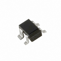
BGA2001,115 NXP Semiconductors, BGA2001,115 Datasheet

BGA2001,115
Specifications of BGA2001,115
934055586115
BGA2001 T/R
Related parts for BGA2001,115
BGA2001,115 Summary of contents
Page 1
DATA SHEET BGA2001 Silicon MMIC amplifier Product specification Supersedes data of 1999 Jul 23 DISCRETE SEMICONDUCTORS M3D124 1999 Aug 11 ...
Page 2
... NXP Semiconductors Silicon MMIC amplifier FEATURES Low current, low voltage Very high power gain Low noise figure Integrated temperature compensated biasing Supply and RF output pin combined. APPLICATIONS RF front end Wideband applications, e.g. analog and digital cellular telephones, cordless telephones (PHS, DECT, etc.) ...
Page 3
... NXP Semiconductors Silicon MMIC amplifier LIMITING VALUES In accordance with the Absolute Maximum Rating System (IEC 134). SYMBOL PARAMETER V supply voltage S I supply current (DC total power dissipation tot T storage temperature stg T operating junction temperature j THERMAL CHARACTERISTICS SYMBOL R thermal resistance from junction to soldering point ...
Page 4
... NXP Semiconductors Silicon MMIC amplifier 100 pF handbook, halfpage L1 GND V S-OUT BGA2001 IN GND Fig.2 Typical application circuit. 12 handbook, halfpage I VS-OUT (mA − ( (5) V VS-OUT VS-OUT ( 1.5 V (6) V VS-OUT VS-OUT ( (7) V VS-OUT VS-OUT ( 2.5 V (8) V VS-OUT VS-OUT Fig.4 Bias current (I VS-OUT ambient temperature with V parameter ...
Page 5
... NXP Semiconductors Silicon MMIC amplifier 30 handbook, halfpage gain (dB MSG 900 MHz. Fig.6 Gain as a function of bias current (I ); typical values. VS-OUT 40 handbook, halfpage gain (dB MSG 2 mA. VS-OUT VS-OUT Fig.8 Gain as a function of frequency; typical values. 1999 Aug 11 MGS609 handbook, halfpage VS-OUT (mA) ...
Page 6
... NXP Semiconductors Silicon MMIC amplifier handbook, full pagewidth unstable region ° 180 f = 900 MHz 2.5 V; VS-OUT = 50 mA; Z VS-OUT 1 1 1.7 dB. handbook, full pagewidth unstable region source ° 180 f = 1800 MHz 2.5 V; VS-OUT = 50 mA; Z VS-OUT 1 1 1.7 dB. ...
Page 7
... NXP Semiconductors Silicon MMIC amplifier handbook, full pagewidth ° 180 = 50 2 mA; Z VS-OUT VS-OUT o Fig.12 Common emitter input reflection coefficient (s handbook, full pagewidth 180 = 50 2 mA; Z VS-OUT VS-OUT o Fig.13 Common emitter forward transmission coefficient (s 1999 Aug 11 ° ° 135 +0.5 +0.2 ...
Page 8
... NXP Semiconductors Silicon MMIC amplifier handbook, full pagewidth ° 180 = 50 2 mA; Z VS-OUT VS-OUT o Fig.14 Common emitter reverse transmission coefficient (s handbook, full pagewidth ° 180 = 50 2 mA; Z VS-OUT VS-OUT o Fig.15 Common emitter output reflection coefficient (s 1999 Aug 11 ° 90 ° 135 3 GHz ...
Page 9
... NXP Semiconductors Silicon MMIC amplifier PACKAGE OUTLINE Plastic surface-mounted package; reverse pinning; 4 leads DIMENSIONS (mm are the original dimensions UNIT max 0.4 0.7 1.1 mm 0.1 0.8 0.3 0.5 OUTLINE VERSION IEC SOT343R 1999 Aug scale 0.25 2.2 1.35 1.3 1.15 0.10 1.8 1 ...
Page 10
... In no event shall NXP Semiconductors be liable for any indirect, incidental, punitive, special or consequential damages (including - without limitation - lost profits, lost savings, business interruption, costs related to the ...
Page 11
... NXP Semiconductors’ specifications such use shall be solely at customer’s own risk, and (c) customer fully indemnifies NXP Semiconductors for any liability, damages or failed product claims resulting from customer design and use of the product for automotive applications beyond NXP Semiconductors’ ...
Page 12
... Interface, Security and Digital Processing expertise Customer notification This data sheet was changed to reflect the new company name NXP Semiconductors, including new legal definitions and disclaimers. No changes were made to the technical content, except for package outline drawings which were updated to the latest version. ...


