RN-111B-EVAL Roving Networks Inc, RN-111B-EVAL Datasheet - Page 3
RN-111B-EVAL
Manufacturer Part Number
RN-111B-EVAL
Description
EVALUATION KIT FOR WIFLY MODULE
Manufacturer
Roving Networks Inc
Type
WiFly 802.11br
Specifications of RN-111B-EVAL
Frequency
2.4GHz
Wireless Frequency
50 Hz to 60 Hz
Interface Type
USB, Serial, SMA
Operating Voltage
5 VDC
Lead Free Status / RoHS Status
Lead free / RoHS Compliant
Lead Free Status / RoHS Status
Lead free / RoHS Compliant, Lead free / RoHS Compliant
Other names
740-1027


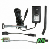
Serial Connection:
1. Connect the Serial cable to the
2. Connect the 10pin ribbon cable to the
3. Connect the other end of the 10pin
4. Move the jumper from USB to serial
5. Plug in the power connector to the
6. Plug the serial cable into the computer.
7. If your computer has a mail DB9
If the hardware is successfully connected, if the green LED on the evaluation board is on and the red LED
on the WiFly module is on (not associated) while the green LED is blinking fast (not connected).
Step 2: Configuring the WiFly Module
The most basic configuration requires only the name (SSID) and channel of the wireless network. The
WiFly module can only associate with one network at a time. It is recommended that you first configure
the WiFly module using an open access point to simplify the setup.
Using the WiFly Utility to configure the WiFly module
NOTE: The WiFly utility only recognizes the USB
connector setup. If you are using the serial connection
you will need to us a terminal emulator program for
configuration and setup.
The WiFly Utility simplifies the task configuring the WiFly
module by detecting the COM port that the USB serial
device is connected to and providing graphical interface
for the WiFly programming language.
1. Start the WiFly Utility
809 University Avenue
development board. The red side of the
ribbon cable should be towards the near
edge of the evaluation board.
WiFly module and evaluation board.
When looking from above, red side of
the ribbon should be towards the edge
of the module
ribbon cable to the WiFly Module, again
the red side of the ribbon cable should
be on the outside edge of the module.
mode. The jumper should be inline with
the length of the evaluation board (See
figure 2)
evaluation board
connector you will need a male to male, null modem cable to complete the connection.
If the USB cable is plugged in and the drivers are
load correctly Windows should recognize the new
•
Los Gatos, CA 95032
•
Tel (408) 395-6539
Fig. 2 Serial cable setup and jumper setting
RN-111B-EVAL
IGRN111B-EVAL 3/10/2009
• info@RovingNetworks.com
Related parts for RN-111B-EVAL
Image
Part Number
Description
Manufacturer
Datasheet
Request
R

Part Number:
Description:
MODULE WIFLY 802.11B SMA
Manufacturer:
Roving Networks Inc
Datasheet:

Part Number:
Description:
MODULE WIFLY 802.11B RP-SMA
Manufacturer:
Roving Networks Inc
Datasheet:

Part Number:
Description:
MODULE WIFLY 802.11B CHIP ANT
Manufacturer:
Roving Networks Inc
Datasheet:

Part Number:
Description:
MODULE WIFLY 802.11B 1/4 WV-WIRE
Manufacturer:
Roving Networks Inc
Datasheet:

Part Number:
Description:
ADAPTER BLUETOOTH FRFLY SRL MALE
Manufacturer:
Roving Networks Inc
Datasheet:

Part Number:
Description:
ADAPTER BLUETOOTH FIREFLY RS422
Manufacturer:
Roving Networks Inc
Datasheet:

Part Number:
Description:
ADAPTER BLUETOOTH FRFLY SRL MALE
Manufacturer:
Roving Networks Inc
Datasheet:

Part Number:
Description:
ADAPTER BLUETOOTH FRFLY SRL MALE
Manufacturer:
Roving Networks Inc
Datasheet:

Part Number:
Description:
RES 11 OHM 1/4W 1% AXIAL
Manufacturer:
Stackpole Electronics Inc
Datasheet:
Part Number:
Description:
RES 11 OHM 1/4W 5% AXIAL
Manufacturer:
Stackpole Electronics Inc
Datasheet:
Part Number:
Description:
RES 11 OHM 1/2W 1% AXIAL
Manufacturer:
Stackpole Electronics Inc
Datasheet:
Part Number:
Description:
RES 11 OHM 1/4W 1% AXIAL
Manufacturer:
Stackpole Electronics Inc
Datasheet:
Part Number:
Description:
RES 11 OHM 1/2W 1% AXIAL
Manufacturer:
Stackpole Electronics Inc
Datasheet:

Part Number:
Description:
MODULE SOCKET BLUETOOTH CLASS1
Manufacturer:
Roving Networks Inc
Datasheet:

Part Number:
Description:
MODULE BLUETOOTH V2.1+EDR
Manufacturer:
Roving Networks Inc
Datasheet: