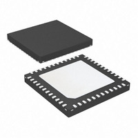
ATA5812-PLQ Atmel, ATA5812-PLQ Datasheet - Page 24

ATA5812-PLQ
Manufacturer Part Number
ATA5812-PLQ
Description
IC TXRX UHF ASK/FSK 1CH 48-QFN
Manufacturer
Atmel
Datasheet
1.ATA5811-PLHC.pdf
(92 pages)
Specifications of ATA5812-PLQ
Frequency
315MHz
Data Rate - Maximum
20kbps
Modulation Or Protocol
ASK, FSK
Applications
Access Control, AMR, RKE
Sensitivity
-116dBm
Voltage - Supply
2.4 V ~ 3.6 V or 4.4 V ~ 6 V
Current - Receiving
10.5mA
Current - Transmitting
10.5mA
Data Interface
PCB, Surface Mount
Antenna Connector
PCB, Surface Mount
Operating Temperature
-40°C ~ 105°C
Package / Case
48-VQFN Exposed Pad, 48-HVQFN, 48-SQFN, 48-DHVQFN
Lead Free Status / RoHS Status
Contains lead / RoHS non-compliant
Power - Output
-
Memory Size
-
Other names
ATA5812-PLQTR
Available stocks
Company
Part Number
Manufacturer
Quantity
Price
Company:
Part Number:
ATA5812-PLQW
Manufacturer:
ATMEL
Quantity:
962
24
ATA5811/ATA5812
To ensure proper start-up behavior the small signal gain and thus the negative resistance pro-
vided by this XTO at start is very large, for example oscillation starts up even in worst case with
a crystal series resistance of 1.5
approximately given by
with Z
Z1 = –j/(2
Z
Z3 = –j/(2
XTAL2 with typically 19 ms at 25°C.
With f
about 2 k . The worst case for technological, supply voltage and temperature variations is then
for C
Due to the large gain at start the XTO is able to meet a very low start-up time. The oscillation
start-up time can be estimated with the time constant
After 10
High if the amplitude is large enough, this sets N_RESET to High and activates the CLK output if
CLK_ON in control register 3 is High (see
tions of the VSOUT and DVCC voltage also have to be fulfilled (see
Figure 7-1 on page
To save current in Idle and sleep mode, the load capacitors partially are switched off in this
modes with S1 and S2 seen in
It is recommended to use a crystal with C
C
Re Z
3
0
=
consists of crystals C
= 1.5 pF to 2.2 pF.
0
------------------------------------------------------------------------------------------------------- -
4
xtocore
XTO
1
, Z
2.2 pF always higher than 1.5 k .
= 13.5 MHz, gm = 19 ms, CL = 9 pF, C
2
2
to 20
as complex impedances at pin XTAL1 and XTAL2 hence
=
f
2
m
Re
f
f
XTO
C
XTO
Z
----------------------------------------------------------------------------------------------------- -
an amplitude detector detects the oscillation amplitude and sets XTO_OK to
m
1
27).
2
Z
Z
C
Re Z
C
3
0
1
+
L1
0
+
in parallel with an internal 110 k resistor hence
) /110 k , gm is the internal transconductance between XTAL1 and
Z
) + 5 and Z2 = –j/(2
Z
2
xtocore
2
+
Figure 6-2 on page
Z
Z
3
3
+
k
+
+
Z
Z
R
1
1
at C
m
Z
Z
Table 9-7 on page
2
2
0
m
2.2 pF with this XTO. The negative resistance is
g
Z
m
3
= 4.0 fF to 7.0 fF, C
0
= 2.2 pF this results in a negative resistance of
g
25.
m
f
XTO
36). Note that the necessary condi-
C
L2
) + 5 .
LN
Figure 6-2 on page 25
= 9 pF, R
m
4689F–RKE–08/06
< 120
and
and


