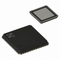
XE1205I074TRLF Semtech, XE1205I074TRLF Datasheet - Page 6

XE1205I074TRLF
Manufacturer Part Number
XE1205I074TRLF
Description
IC TXRX 433/868/915MHZ 48-VQFN
Manufacturer
Semtech
Datasheet
1.XE1205SKC915XE1.pdf
(48 pages)
Specifications of XE1205I074TRLF
Frequency
180MHz Center
Data Rate - Maximum
152.3kbps
Modulation Or Protocol
FSK
Applications
AMR, ISM, Home Automation, Process Control
Power - Output
0 ~ 15dBm
Sensitivity
-121dBm
Voltage - Supply
2.4 V ~ 3.6 V
Current - Receiving
14mA
Current - Transmitting
62mA
Data Interface
PCB, Surface Mount
Antenna Connector
PCB, Surface Mount
Operating Temperature
-40°C ~ 85°C
Package / Case
48-VQFN
Receiving Current
14mA
Transmitting Current
62mA
Data Rate
4.8Kbps
Modulation Type
FSK
Rf Ic Case Style
VQFN
No. Of Pins
48
Supply Voltage Range
2.4V To 3.6V
Operating Temperature (min)
-40C
Operating Temperature (max)
85C
Operating Temperature Classification
Industrial
Operating Supply Voltage (typ)
2.5/3.3V
Operating Supply Voltage (max)
3.6V
Rohs Compliant
Yes
Lead Free Status / RoHS Status
Lead free / RoHS Compliant
Memory Size
-
Lead Free Status / Rohs Status
Compliant
Other names
XE1205I074TR
© Semtech 2008
Symbol
ACR_25
ACR_50
BR
RFOP
ACP
FR
TS_SRE
TS_STR
TS_FS
TS_RE
TS_TR
TS_RFSW Receiver recovery time when
TS_TFSW Transmitter recovery time when
TS_RSSI
TS_OS
TS_FEI
XTAL
FSTEP
VTHR
SPR
VIH
VIL
VOH
VOL
(1)
(2)
(3)
(4)
(5)
Additional bandwidths can be selected with special settings described in section 7.2.8.
With additional bandwidth configuration register settings as described in sections 5.2.6 and 7.2.8.
SPR strongly depends on the design of the application board and the choice of the external components. Values down to -70 dBm can be
achieved with careful design.
304.7 kbit/s achievable with additional register settings as described in section 6. The 304.7kpbs max bit rate is guaranteed by validation.
The max bit rate guaranteed by production test is 152.3 kbit/s
RSSI also available in mode B with higher thresholds as described in section 5.2.3.4
Description
Receiver adjacent channel rejection
ratio at 25 kHz
Receiver adjacent channel rejection
ratio at 50 kHz
Bit rate
RF output power
Transmitter adjacent channel power
(measured at 25 kHz offset)
Synthesizer frequency range
Receiver wake-up time
Transmitter wake-up time
Frequency synthesizer wake-up
time
Receiver wake-up time
Transmitter wake-up time
switching between 2 channels
switching between 2 channels
RSSI wake-up time
Quartz oscillator wake-up time
FEI wake-up time
Quartz oscillator frequency
Frequency synthesizer step
Equivalent input thresholds
of the RSSI
Spurious emission in receiver mode
Digital input level high
Digital input level low
Digital output level high
Digital output level low
Table 4: Electrical Specifications
Conditions
funw = f
Pw=-110 dBm, mode A
BW (SSB) = 10 kHz
BW (SSB) = 8 kHz (2)
funw = f
Pw=-110 dBm, mode A
Programmable
Programmable
RFOP1
RFOP2
RFOP3
RFOP4
Pre-filter enabled
(RFOP3 mode)
Measurement conditions as
defined by EN 300 220-1 V1.3.1
Programmable
Quartz oscillator enabled
Quartz oscillator enabled
Quartz oscillator enabled
Frequency synthesizer enabled
Frequency synthesizer enabled
Between 2 channels at 1 MHz
from each other
Between 2 channels at 1 MHz
from each other
Receiver enabled
Fundamental
3
Receiver enabled
Fundamental or third harmonic
Exact step is XTAL / 77’824
Mode A
VTHR2
VTHR3
Mode A, high range:VTHR1
VTHR2
VTHR3
(3)
% VDD
% VDD
% VDD
% VDD
rd
overtone
(5)
LO
LO
, low range:VTHR1
6
+ 25 kHz single tone
+ 50 kHz single tone
Min
+12
433
863
902
1.2
+2
+7
75
75
-3
-
-
-
-
-
-
-
-
-
-
-
-
-
-
-
-
-
-
-
-
-
-
-
-
-
-
Typ
2/BR
-110
-105
-100
+10
+15
700
250
200
500
100
700
150
500
-95
-90
-85
-65
20
30
40
+5
39
0
1
7
-
-
-
-
-
-
-
-
-
-
XE1205
304.7
Max
435
870
928
850
350
250
600
150
250
-37
1.5
25
25
2
-
-
-
-
-
-
-
-
-
-
-
-
-
-
-
-
-
-
-
-
www.semtech.com
(4)
kbit/s
dBc
dBm
dBm
dBm
dBm
dBm
MHz
MHz
MHz
MHz
dBm
dBm
dBm
dBm
dBm
dBm
dBm
Unit
dBc
dBc
ms
ms
ms
ms
Hz
us
us
us
us
us
us
us
%
%
%
%


