GS-BT2416C1.H STMicroelectronics, GS-BT2416C1.H Datasheet
GS-BT2416C1.H
Specifications of GS-BT2416C1.H
GS-BT2416C1.H


Related parts for GS-BT2416C1.H


GS-BT2416C1.H Summary of contents
Page 1
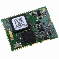
... Class 1 modules enable wireless communication with other Bluetooth 100 m away. The GS-BT2416C1.H integrates on a unique FR4 PCB support: BT 1.2 radio and baseband, memory, 32 kHz and 13 MHz oscillator, Vreg as well PA function. The module ...
Page 2
... Integrate firmware . . . . . . . . . . . . . . . . . . . . . . . . . . . . . . . . . . . . . . . . . . . 7 5.1 Features . . . . . . . . . . . . . . . . . . . . . . . . . . . . . . . . . . . . . . . . . . . . . . . . . . . 7 5.2 Command interface . . . . . . . . . . . . . . . . . . . . . . . . . . . . . . . . . . . . . . . . . . 7 5.3 Usage scenarios . . . . . . . . . . . . . . . . . . . . . . . . . . . . . . . . . . . . . . . . . . . . 7 6 Application information . . . . . . . . . . . . . . . . . . . . . . . . . . . . . . . . . . . . . . 8 6.1 Antenna reference . . . . . . . . . . . . . . . . . . . . . . . . . . . . . . . . . . . . . . . . . . . 9 7 Block diagram . . . . . . . . . . . . . . . . . . . . . . . . . . . . . . . . . . . . . . . . . . . . . 10 8 Pin settings . . . . . . . . . . . . . . . . . . . . . . . . . . . . . . . . . . . . . . . . . . . . . . . 11 8.1 Pin connections . . . . . . . . . . . . . . . . . . . . . . . . . . . . . . . . . . . . . . . . . . . . 11 8.2 Pin descriptions . . . . . . . . . . . . . . . . . . . . . . . . . . . . . . . . . . . . . . . . . . . . 12 9 Soldering . . . . . . . . . . . . . . . . . . . . . . . . . . . . . . . . . . . . . . . . . . . . . . . . . 15 10 Mechanical dimensions . . . . . . . . . . . . . . . . . . . . . . . . . . . . . . . . . . . . . 16 11 Ordering information scheme . . . . . . . . . . . . . . . . . . . . . . . . . . . . . . . . 18 12 Revision history . . . . . . . . . . . . . . . . . . . . . . . . . . . . . . . . . . . . . . . . . . . 19 2/19 GS-BT2416C1.H ...
Page 3
... GS-BT2416C1.H 1 Certifications ● CE compliant (IMQ Exp. opinion 0081-AREF00017) – Safety EN60950-1 (2001) – EMC EN301 489 17V1.2.1 – Radio ES 300 328 V1.6. – FCC certified on GS-BT2416C1DB (for a more exhaustive explanation, please refer to GS-BT2416C1DB application note) – FCC ID: S9NBT2416C1DB ● BQB compliant ...
Page 4
... DD Operating ambient T stg temperature 4/19 Table 1) indicate limits beyond which damage to the device Table 2) define the limits for functional operation and parametric Parameter Parameter Conditions - 20 °C < T < 70 °C GS-BT2416C1.H Values Unit Min Max 4 V Vss -0.5 Vdd+0 -40 +85 °C 240 ...
Page 5
... GS-BT2416C1.H 3 Electrical characteristics 3.1 DC I/O specification Table 3. DC input / output specification Symbol V Low level input voltage il V High level input voltage ih V Schmitt trigger hysteresis hyst V Low level output voltage ol V High level output voltage oh ® 4 Bluetooth Table 4. Bluetooth Symbol CHs ...
Page 6
... A Parameter Conditions 2.402 GHz 2.441 GHz 2.480 GHz lM- lM-Nl ≥ 3 @BER 0.1 % Parameter Conditions DH1 data packet DH3 data packet DH5 data packet Drift rate GS-BT2416C1.H Min Typ Max Unit 18 20 dBm 18 20 dBm 18 20 dBm - 36 dBm - 44 dBm - 84 dBm ...
Page 7
... GS-BT2416C1.H 5 Integrate firmware The GS-BT2416C1.H includes customer framework up to HCI (host control interface) Figure 1. HCI firmware implementation Serial Interface Layer UART, USB, … SCO channels – Synchronous Connection Oriented Hardware Layer Set up the physical connection 5.1 Features The module with HCI embedded is interoperable with qualified BT stack protocols and suitable for any BT applications ...
Page 8
... Keep the RF ground separate from the module supply voltage ground; the two grounds are already connected inside the module in one point, see below a possible implementation. Figure 2. Module foot print 8/19 RF gnd Module foot print Supply voltage GND GS-BT2416C1.H ...
Page 9
... GS-BT2416C1.H 6.1 Antenna reference RF output pin must be connected to an antenna which could be: ● Antenna directly printed on the pcb ● Integrated antenna as, for example, antenova ANCV12G44SAA127, pulse W3008, Yageo CAN4311153002451K. ● External antenna connected by means a SMA connector Figure 3. Antenna on PCB ● Despite of the type of antenna chosen, the connection between the RF out pin and the antenna must be executed in such a way that the connection trace must be matched to have characteristic impedance (Z0 Ω ...
Page 10
... Block diagram 7 Block diagram Figure 7. Block diagram UART USB PCM SPI I²C GPIO 10/19 32kHz 32kHz XTAL XTAL STLC2416 STLC2150 Baseband Radio chip ARM7 proc GS-BT2416C1.H RF antenna PA SW Filter LNA ...
Page 11
... GS-BT2416C1.H 8 Pin settings 8.1 Pin connections Figure 8. Pin connection diagram Pin settings 11/19 ...
Page 12
... I/O Not to be used internally used for RX/TX switch 15 ---- I/O Not to be used internally used for TX gain setting 16 ---- I/O Not to be used internally used for TX gain setting 17 ---- I/O Not to be used internally used for TX gain setting 18 ---- I/O Not to be used internally used for TX gain setting 12/19 GS-BT2416C1.H Description ...
Page 13
... GS-BT2416C1.H Table 7. Pin descriptions (continued) Pin N° Name I/O Test interface signals 19 TDI --- JTAG pin 20 TDO --- JTAG pin 21 TMS --- JTAG pin 22 NTRST --- JTAG pin 23 TCK --- JTAG pin If not used connect to VSS1 I2C interface signals 24 I2C_dat I/O I2C bus interface data to be connected to VDD with 10 kΩ resistor ...
Page 14
... Time within 5 °C of actual peak temperature (t Ramp down rate Time from 25 °C to peak temperature Figure 9. Soldering 14/ SMAX Preheat min) S max GS-BT2416C1.H PB free assembly 3 °C / sec max 150 °C 200 °C 60 – 100 sec 217 °C 40 – 70 sec 240 + 0 °C 10 – 20 sec 6 °C / sec 8 minutes max ...
Page 15
... GS-BT2416C1.H 10 Mechanical dimensions In order to meet environmental requirements, ST offers these devices in ECOPACK® packages. These packages have a lead-free second level interconnect. The category of second level interconnect is marked on the package and on the inner box label, in compliance with JEDEC Standard JESD97. The maximum ratings related to soldering conditions are also marked on the inner box label ...
Page 16
... Mechanical dimensions Figure 11. Land pattern 16/19 GS-BT2416C1.H ...
Page 17
... GS-BT2416C1.H 11 Ordering information scheme Table 9. Ordering information scheme ® Bluetooth modules V 1.2 compliant Class 1 Embedded HCI Ordering information scheme GS-BT 2416 C1 H 17/19 ...
Page 18
... Revision history 12 Revision history Table 10. Revision history Date 31-Aug-2006 27-May-2008 18/19 Revision 1 First release Updated: Cover page 2 Added: Section 9 on page 14 GS-BT2416C1.H Changes ...
Page 19
... GS-BT2416C1.H Information in this document is provided solely in connection with ST products. STMicroelectronics NV and its subsidiaries (“ST”) reserve the right to make changes, corrections, modifications or improvements, to this document, and the products and services described herein at any time, without notice. All ST products are sold pursuant to ST’s terms and conditions of sale. ...