UGWP2USHN33 Unigen Corp, UGWP2USHN33 Datasheet - Page 9
UGWP2USHN33
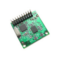
Manufacturer Part Number
UGWP2USHN33
Description
MODULE JUNO-LPA-J 6935 MINI-COAX
Manufacturer
Unigen Corp
Datasheet
1.UGWKJULCYA1-EK.pdf
(17 pages)
Specifications of UGWP2USHN33
Frequency
2.4GHz ~ 2.48GHz
Data Rate - Maximum
62.5kbps
Modulation Or Protocol
DSSS
Power - Output
200mW
Sensitivity
-95dBm
Voltage - Supply
2.7 V ~ 3.6 V
Current - Receiving
60mA
Current - Transmitting
140mA
Data Interface
Connector, Mirrored 2 x 6 Header
Antenna Connector
Coaxial
Operating Temperature
-20°C ~ 70°C
Package / Case
Module
Lead Free Status / RoHS Status
Lead free / RoHS Compliant
Applications
-
Memory Size
-
Other names
784-1009


Solutions for a Real Time World
I
Industry Canada regulatory approval typically conforms to the FCC in terms of emission levels
and other regulatory requirements. It is the position of the Industry Canada agency that the
OEM primarily responsibility for ensuring end product compliance. Unigen as grantee and
supplier of the module maintains responsibility for the Modular Approved design.
Design Criteria for Modular Approval
General Conditions
The following conditions must be strictly adhered to for modular approval:
The UGWR2US may not be altered or modified in any way by the OEM or other integrator(s).
Additionally, no component(s) may be added which change the radio frequency (RF)
characteristics.
characteristics, or other items commonly associated with RF devices.
components; passive and active (such as RF filters, RF amplifiers, RF switches, etc).
Additionally, no RF components may be placed between the RF output of the UGWR2US and
the antenna(e) except the RF interconnect transmission line.
Antennae
The antennae listed in the UGWR2US datasheet have been qualified and approved for use
under the Modular Approval certification. These antennae are designed to be compatible with
the RF transmission line impedance and frequency range of the UGWR2US. These antennae
may not be modified or altered in any way from the original design as represented in the
antenna datasheets as supplied by the manufacturer.
The antennas selected have been specifically tested with the UGWR2US, and they are certified
through the regulatory agencies in the US, Canada, and European Union for authorized use.
Use of antennas in a platform other than the antennas selected by Unigen voids the MA grant
for that platform.
Antenna Interconnect & Impedance
Unigen has pre-qualified antennas that integrate the connectors, transmission line and the antenna.
UGWR2US requires the use of a ½ dipole, 2.4~2.5GHz frequency range, with a VSWR no greater
than 2.0 and having a maximum output no greater than +2dBi The transmission line must be
designed to be 50-Ohm impedance.
UM-UGWR2US
support@unigen.com
http://www.unigen.com
NDUSTRY
1. No modification to the module including the circuitry is permitted
2. The design criteria including antennas, interconnects and transmission line
3. Testing of the final device configuration for Digital Emissions Compliance
C
ANADIAN
These include unintentional or spurious emissions, immunity, ESD
R
EGULATORY
Copyright Unigen Corporation, 2004
WirelessUSB™ - UGWR2US
A
9
PPROVAL
45388 Warm Springs Blvd. Fremont, CA 94539
TEL: (510) 668.2088 FAX: (510) 661.2788
This includes all
Toll Free: (800) 826.0808
User Manual
Related parts for UGWP2USHN33
Image
Part Number
Description
Manufacturer
Datasheet
Request
R


Part Number:
Description:
EVALUATION KIT ECHO 400
Manufacturer:
Unigen Corp
Datasheet:

Part Number:
Description:
EVALUATION KIT ECHO 800
Manufacturer:
Unigen Corp
Datasheet:

Part Number:
Description:
EVALUATION KIT ECHO 900
Manufacturer:
Unigen Corp
Datasheet:


Part Number:
Description:
EVALUATION KIT JUNO-LPA
Manufacturer:
Unigen Corp
Datasheet:


Part Number:
Description:
EVALUATION KIT NEMO
Manufacturer:
Unigen Corp
Datasheet:

Part Number:
Description:
EVALUATION KIT PAN 400
Manufacturer:
Unigen Corp
Datasheet:

Part Number:
Description:
EVALUATION KIT PAN 800
Manufacturer:
Unigen Corp
Datasheet:

Part Number:
Description:
EVALUATION KIT PAN 900
Manufacturer:
Unigen Corp
Datasheet: