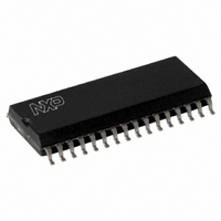
CLRC63201T/0FE,112 NXP Semiconductors, CLRC63201T/0FE,112 Datasheet - Page 88

CLRC63201T/0FE,112
Manufacturer Part Number
CLRC63201T/0FE,112
Description
IC I.CODE HS READER 32-SOIC
Manufacturer
NXP Semiconductors
Series
I-Coder
Specifications of CLRC63201T/0FE,112
Rf Type
Read Only
Frequency
13.56MHz
Features
ISO14443-A, ISO14443-B, ISO15693, ISO18000-3
Package / Case
32-SOIC (0.300", 7.50mm Width)
Product
RFID Readers
Operating Temperature Range
- 25 C to + 85 C
Lead Free Status / RoHS Status
Lead free / RoHS Compliant
Lead Free Status / RoHS Status
Lead free / RoHS Compliant, Lead free / RoHS Compliant
Other names
568-2199-5
935269690112
CLRC632
CLRC63201TD
935269690112
CLRC632
CLRC63201TD
Available stocks
Company
Part Number
Manufacturer
Quantity
Price
Company:
Part Number:
CLRC63201T/0FE,112
Manufacturer:
IR
Quantity:
3 400
Part Number:
CLRC63201T/0FE,112
Manufacturer:
NXP/恩智浦
Quantity:
20 000
NXP Semiconductors
CLRC632_35
Product data sheet
PUBLIC
11.3.1.2 RF channel redundancy and framing
11.3.1.3 Transmission of frames of more than 64 bytes
11.3.2 Receive command 16h
Each transmitted ISO/IEC 15693 frame consists of a Start Of Frame (SOF) pattern,
followed by the data stream and is closed by an End Of Frame (EOF) pattern. All I-CODE1
command frames consists of a start pulse followed by the data stream. The I-CODE1
commands have a fixed length and do not need an EOF. The phases of the transmission
sequence are monitored using the PrimaryStatus register’s ModemState[2:0] bits; see
Section 11.2.4 on page
Depending on the ChannelRedundancy register TxCRCEn bit setting, the CRC is
calculated and appended to the data stream. The CRC is calculated using the
ChannelRedundancy register settings.
To generate frames of more than 64 bytes of data, the microprocessor has to write data to
the FIFO buffer while the Transmit command is active. The state machine checks the FIFO
buffer status when it starts transmitting the last bit of the data stream (the check time is
shown in
As long as the internal accept further data signal is logic 1 further data can be written to
the FIFO buffer. The CLRC632 appends this data to the data stream transmitted using the
RF interface.
If the internal accept further data signal is logic 0 the transmission terminates. All data
written to the FIFO buffer after accept further data signal was set to logic 0 is not
transmitted, however, it remains in the FIFO buffer.
Table 144. Receive command 16h
The Receive command activates the receiver circuitry. All data received from the RF
interface is written to the FIFO buffer. The Receive command can be started either by the
microprocessor or automatically during execution of the Transceive command.
Command
Receive
Fig 20. Timing for transmitting byte oriented frames
accept further data
check FIFO empty
Figure 20
FIFOLength[6:0]
TxLastBits[2:0]
FIFO empty
TxData
Value
16h
with arrows).
Rev. 3.5 — 10 November 2009
85.
7
Multiple protocol contactless reader IC (MIFARE/I-CODE1)
0
Action
activates receiver circuitry
073935
0x01
TxLastBits = 0
7
0
Arguments
and data
-
0x00
CLRC632
© NXP B.V. 2009. All rights reserved.
7
Returned data
data stream
001aak619
88 of 126


