MEO550-02DA IXYS, MEO550-02DA Datasheet
MEO550-02DA
Manufacturer Part Number
MEO550-02DA
Description
DIODE FRED 200V 582A 150NS
Manufacturer
IXYS
Datasheet
1.MEO550-02DA.pdf
(2 pages)
Specifications of MEO550-02DA
Voltage - Forward (vf) (max) @ If
1.25V @ 520A
Current - Reverse Leakage @ Vr
5mA @ 200V
Current - Average Rectified (io) (per Diode)
582A
Voltage - Dc Reverse (vr) (max)
200V
Reverse Recovery Time (trr)
200ns
Diode Type
Standard
Speed
Fast Recovery =< 500ns, > 200mA (Io)
Diode Configuration
Single
Mounting Type
Chassis Mount
Package / Case
Y4-M6
Rectifier Type
Switching Diode
Configuration
Single
Peak Rep Rev Volt
200V
Avg. Forward Curr (max)
582A
Rev Curr
5000uA
Peak Non-repetitive Surge Current (max)
5280A
Forward Voltage
1.25V
Operating Temp Range
-40C to 150C
Package Type
Y4-M6
Rev Recov Time
200ns
Operating Temperature Classification
Automotive
Mounting
Screw
Pin Count
2
Vrrm, (v)
200
Ifavm, D = 0.5, Total, (a)
582
@ Tc, (°c)
75
Ifrms, (a)
822
Ifsm, 10 Ms, Tvj = 45°c, (a)
4800
Vf, Max, Tvj = 150°c, (v)
1.08
@ If, (a)
520
Trr, Typ, Tvj =25°c, (ns)
150
Irm , Max, Tvj = 100°c, (a)
15
@ -di/dt, (a/µs)
200
Rthjc, Max, (k/w)
0.071
Ptot, Max, (w)
1750
Package Style
Y4-M6
Lead Free Status / RoHS Status
Lead free / RoHS Compliant
Other names
Q1147009A
Available stocks
Company
Part Number
Manufacturer
Quantity
Price
Company:

Part Number:
MEO550-02DA
Manufacturer:
IXYS
Quantity:
1 000
Part Number:
MEO550-02DA
Quantity:
60


© 2000 IXYS All rights reserved
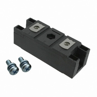
Fast Recovery
Epitaxial Diode
(FRED) Module
Symbol
I
I
I
I
I
T
T
T
P
V
M
d
d
a
Weight
Symbol
I
V
V
r
R
R
t
I
Data according to IEC 60747
IXYS reserves the right to change limits, test conditions and dimensions
FRMS
FAVM
FRM
FSM
2
R
rr
RM
T
V
200
t
VJ
stg
Smax
S
A
tot
ISOL
F
T0
thJH
thJC
d
RSM
V
I
FAVM
ÿÿ
rating includes reverse blocking losses at T
V
200
RRM
V
T
T
t
T
T
T
T
T
50/60 Hz, RMS t = 1 min
I
Mounting torque (M6)
Terminal connection torque (M6)
Creep distance on surface
Strike distance through air
Maximum allowable acceleration
T
T
T
I
I
For power-loss calculations only
DC current
DC current
I
V
-di/dt =
Test Conditions
Test Conditions
P
ISOL
F
F
F
C
C
VJ
VJ
VJ
VJ
C
VJ
VJ
VJ
R
< 10 ms; rep. rating, pulse width limited by T
=
=
=
=
= 25°C
=
=
= 45°C;
= 150°C; t = 10 ms (50 Hz), sine
= 45°C;
= 150°C; t = 10 ms (50 Hz), sine
= 25°C
= 25°C
= 125°C
£ 1 mA
300
520
500
100
75
75
200
°C
°C; rectangular, d = 0.5
A;
A;
V
A
Type
MEO 550-02DA
A/ms
t = 10 ms (50 Hz), sine
t = 8.3 ms (60 Hz), sine
t = 8.3 ms (60 Hz), sine
t = 10 ms (50 Hz), sine
t = 8.3 ms (60 Hz), sine
t = 8.3 ms (60 Hz), sine
V
V
V
T
T
T
T
VJ
VJ
VJ
VJ
R
R
R
t = 1 s
= V
= 0.8 • V
= 0.8 • V
= 125°C
= 25°C
= 125°C
= 25°C
RRM
T
T
T
VJ
VJ
VJ
= 100°C
= 25°C
= 100°C
RRM
RRM
VJM
, V
R
= 0.6 V
RRM
Characteristic Values (per diode)
, duty cycle d = 0.5
MEO 550-02 DA
VJM
150
typ.
2.25-2.75/20-25
4.50-5.50/40-48
3
Maximum Ratings
-40...+150
-40...+125
115200
117100
max.
93300
94800
0.114
0.071
4800
5280
4320
4750
1750
3000
3600
2880
12.7
1.10
1.25
0.52
1.06
0.84
1.08
822
582
110
150
160
200
9.6
50
15
5
4
9
Nm/lb.in.
Nm/lb.in.
1
m/s
K/W
K/W
mm
mm
mW
A
A
A
A
mA
mA
mA
V~
V~
°C
°C
°C
ns
W
A
A
A
A
A
A
A
g
V
V
V
V
V
A
A
2
2
2
2
s
s
s
s
2
V
I
t
Features
Applications
Advantages
Dimensions in mm (1 mm = 0.0394")
FAVM
rr
International standard package
with DCB ceramic base plate
Planar passivated chips
Short recovery time
Low switching losses
Soft recovery behaviour
Isolation voltage 3600 V~
UL registered E 72873
Antiparallel diode for high frequency
switching devices
Free wheeling diode in converters
and motor control circuits
Inductive heating and melting
Uninterruptible power supplies (UPS)
Ultrasonic cleaners and welders
High reliability circuit operation
Low voltage peaks for reduced
protection circuits
Low noise switching
Low losses
RRM
= 200 V
= 582 A
= 150 ns
1
3
1 - 2
Related parts for MEO550-02DA
Image
Part Number
Description
Manufacturer
Datasheet
Request
R


Part Number:
Description:
HiPerFET Power MOSFETs
Manufacturer:
IXYS Corporation
Datasheet:
Part Number:
Description:
J-K-Type Flip-Flop
Manufacturer:
IXYS Corporation
Datasheet:
Part Number:
Description:
HiPerRF Power MOSFETs
Manufacturer:
IXYS Corporation
Datasheet:
Part Number:
Description:
Rectifier Module for Three Phase Power Factor Correction
Manufacturer:
IXYS Corporation
Datasheet:
Part Number:
Description:
Thyristor Modules Thyristor/Diode Modules
Manufacturer:
IXYS Corporation
Datasheet:
Part Number:
Description:
Thyristor Modules Thyristor/Diode Modules
Manufacturer:
IXYS Corporation
Datasheet:
Part Number:
Description:
Thyristor Modules Thyristor/Diode Modules
Manufacturer:
IXYS Corporation
Datasheet:
Part Number:
Description:
Thyristor Modules Thyristor/Diode Modules
Manufacturer:
IXYS Corporation
Datasheet:
Part Number:
Description:
Thyristor Modules /Diode Modules
Manufacturer:
IXYS Corporation
Datasheet:
Part Number:
Description:
Thyristor Modules /Diode Modules
Manufacturer:
IXYS Corporation
Datasheet:
Part Number:
Description:
Thyristor Modules Thyristor/Diode Modules
Manufacturer:
IXYS Corporation
Datasheet:
MEO550-02DA Summary of contents
Page 1
... 200 -di/ rating includes reverse blocking losses at T FAVM Data according to IEC 60747 IXYS reserves the right to change limits, test conditions and dimensions © 2000 IXYS All rights reserved MEO 550- Maximum Ratings 822 582 2880 VJM 4800 5280 4320 4750 ...
Page 2
... T VJ Fig. 4 Dynamic parameters versus junction temperature T 1 K/W 0 thJH thJS 0.01 0.001 0.001 0.01 Fig. 7 Transient thermal impedance junction to heatsink © 2000 IXYS All rights reserved 3 100° 100V R 2.5 I =1100A 550A F 2 275A F 1.5 1.0 0.5 0.0 ...