VSKTF200-12HJ Vishay, VSKTF200-12HJ Datasheet - Page 5
VSKTF200-12HJ
Manufacturer Part Number
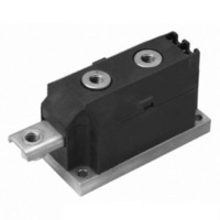
VSKTF200-12HJ
Description
SCR DBL 2SCR 1200V 200A MAGNAPAK
Manufacturer
Vishay
Specifications of VSKTF200-12HJ
Structure
Series Connection - All SCRs
Number Of Scrs, Diodes
2 SCRs
Voltage - Off State
1200V
Current - Gate Trigger (igt) (max)
200mA
Current - On State (it (av)) (max)
200A
Current - On State (it (rms)) (max)
444A
Current - Non Rep. Surge 50, 60hz (itsm)
7600A, 8000A
Current - Hold (ih) (max)
600mA
Mounting Type
Chassis Mount
Package / Case
3-MAGN-A-PAK™
Rated Repetitive Off-state Voltage Vdrm
1200 V
Off-state Leakage Current @ Vdrm Idrm
50 mA
Holding Current (ih Max)
6000 mA
Mounting Style
Screw
Breakover Current Ibo Max
8000 A
Gate Trigger Current (igt)
200 mA
Gate Trigger Voltage (vgt)
3 V
Repetitive Peak Forward Blocking Voltage
1200 V
Lead Free Status / RoHS Status
Contains lead / RoHS non-compliant
Other names
*IRKTF200-12HJ
IRKTF200-12HJ
IRKTF200-12HJ
IRKTF200-12HJ
IRKTF200-12HJ


Document Number: 94422
Revision: 19-Jul-10
10000
Fig. 5 - Maximum Non-Repetitive Surge Current
Fig. 6 - Maximum Non-Repetitive Surge Current
1000
Fig. 7 - On-State Voltage Drop Characteristics
7000
6000
5000
4000
3000
8000
7000
6000
5000
4000
3000
Numb er Of Equa l Amplitude Half Cyc le Current Pulses (N)
100
0.01
1
1
VSK.F 200.. S eries
Per Junction
VSK.F200.. S eries
Per Junction
Instantaneous On-state Voltage (V)
Ma ximum Non Rep etitive S urge Current
Of Conduction May Not Be Maintained.
At Any Rated Load Condition And With
2
Rated V
Versus Pulse T rain Duration. Control
Pulse T rain Duration (s)
3
R RM
DiodesAmericas@vishay.com, DiodesAsia@vishay.com,
For technical questions within your region, please contact one of the following:
No Voltage R eap plied
R ated V
Fast Thyristor/Diode and Thyristor/Thyristor
Applied Following S urge.
T = 25°C
T = 125°C
0.1
10
4
J
J
VSK.F200.. Series
Per Junc tion
(MAGN-A-PAK Power Modules), 200 A
@ 60 Hz 0.0083 s
@ 50 Hz 0.0100 s
Initial T = 125°C
Initial T = 125°C
R RM
5
R eapplied
J
J
6
100
1
7
Fig. 10 - Reverse Recovery Current Characteristics
Fig. 9 - Reverse Recovery Charge Characteristics
Fig. 8 - Thermal Impedance Z
0.001
DiodesEurope@vishay.com
0.01
320
300
280
260
240
220
200
180
160
140
120
100
180
150
120
0.1
80
90
60
30
R ate Of Fall Of Forward Current - di/ dt (A/ µs )
0.001
R ate Of Fall Of Forward Current - di/ dt (A/ µs )
1
10 20 30 40 50 60 70 80 90 100
10 20 30 40 50 60 70 80 90 100
S teady S tate Value:
R
(DC Operation)
thJC
S quare Wave Puls e Duration (s)
0.01
= 0.125 K/ W
I
T M
Vishay Semiconductors
VSK.F200..P Series
I
T M
= 1000 A
0.1
= 1000A
300 A
200 A
100 A
500 A
500A
300A
200A
100A
VSK.F 200.. S eries
Per Junc tion
VSK.F200.. S eries
T = 125°C
VSK.F200.. S eries
T = 125°C
1
J
J
thJC
Characteristics
10
www.vishay.com
100
5
Related parts for VSKTF200-12HJ
Image
Part Number
Description
Manufacturer
Datasheet
Request
R

Part Number:
Description:
Fast Thyristor/Diode and Thyristor/Thyristor (MAGN-A-PAK Power Modules), 200 A
Manufacturer:
VISHAY [Vishay Siliconix]
Datasheet:

Part Number:
Description:
SCR DBL 2SCR 800V 200A MAGNAPAK
Manufacturer:
Vishay
Datasheet:
Part Number:
Description:
SCR DBL 2SCR 800V 200A MAGNAPAK
Manufacturer:
Vishay
Datasheet:
Part Number:
Description:
SCR DBL 2SCR 1200V 200A MAGNAPAK
Manufacturer:
Vishay
Datasheet:

Part Number:
Description:
SCR Modules 200 Amp 800 Volt 444 Amp IT(RMS)
Manufacturer:
Vishay
Datasheet:
Part Number:
Description:
SCR Modules 200 Amp 1200 Volt 444 Amp IT(RMS)
Manufacturer:
Vishay
Datasheet:
Part Number:
Description:
Fast Thyristor/Diode and Thyristor/Thyristor
Manufacturer:
Vishay Siliconix
Datasheet:
Part Number:
Description:
357-036-542-201 CARDEDGE 36POS DL .156 BLK LOPRO
Manufacturer:
Vishay
Datasheet:
Part Number:
Description:
357-036-542-201 CARDEDGE 36POS DL .156 BLK LOPRO
Manufacturer:
Vishay
Datasheet:
Part Number:
Description:
357-036-542-201 CARDEDGE 36POS DL .156 BLK LOPRO
Manufacturer:
Vishay
Datasheet:
Part Number:
Description:
357-036-542-201 CARDEDGE 36POS DL .156 BLK LOPRO
Manufacturer:
Vishay
Datasheet:
Part Number:
Description:
357-036-542-201 CARDEDGE 36POS DL .156 BLK LOPRO
Manufacturer:
Vishay
Datasheet:
Part Number:
Description:
357-036-542-201 CARDEDGE 36POS DL .156 BLK LOPRO
Manufacturer:
Vishay
Datasheet:
Part Number:
Description:
357-036-542-201 CARDEDGE 36POS DL .156 BLK LOPRO
Manufacturer:
Vishay
Datasheet:
Part Number:
Description:
357-036-542-201 CARDEDGE 36POS DL .156 BLK LOPRO
Manufacturer:
Vishay
Datasheet: