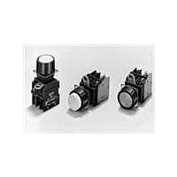
A22-SW-11M Omron, A22-SW-11M Datasheet - Page 24

A22-SW-11M
Manufacturer Part Number
A22-SW-11M
Description
SWITCH PB MUSH MOM SPST-NO/C WHT
Manufacturer
Omron
Series
A22r
Type
Standardr
Specifications of A22-SW-11M
Circuit
DPST (1-NO, 1-NC)
Switch Function
On-Mom, Off-Mom
Contact Rating @ Voltage
10A @ 110VAC
Actuator Type
Mushroom Button
Mounting Type
Panel Mount
Termination Style
Screw Terminal
Contact Form
SPST - NC-NO
Contact Rating
10 mAmps
Actuator
Round, Mushroom
Mounting Style
Panel
Illumination
Illuminated
Illumination Color
White
Body Shape
Square
Dielectric Strength
2500 Volts
Insulation Resistance
100 MOhms
Mounting Angle
Straight
Operating Force
29.4 N
Water / Moisture Rating
IP65
Lead Free Status / RoHS Status
Lead free / RoHS Compliant
Illumination Type, Color
-
Illumination Voltage (nominal)
-
Lead Free Status / Rohs Status
Lead free / RoHS Compliant
Other names
A22SW11M
Application
Mounting to the Panel
Panel Hole Dimensions
Panel hole dimensions are given below.
Recommended panel thickness: 1 to 5 mm.
For 25-dia. holes, always use 25-dia. Rings. (Since the cutout
dimensions are large, IP65 cannot be guaranteed unless 25-dia.
Rings are used.)
If outer surface treatment such as coating is performed for the
panel, the panel dimensions after outer surface treatment must
meet the specified panel dimensions.
Not Using a Lock Ring
22.3
+0.4
0
22 dia.
http://www.ia.omron.com/
Using a Lock Ring
3.2
+0.2
0
22.3
+0.4
0
25
+0.5
0
25 dia.
Matrix Installation
1. The following panel hole dimensions
2. The following panel hole dimensions
For 1. above:
For 2. above:
Note: 1. The above dimensions are the minimum dimensions for when the wires
Mounting the Operation Unit on the Panel
Pitches A and B between the centers of the mounting holes are as follows:
Type of crimp terminal
Bare crimp terminals
Crimp terminals with
insulating sheath
Insert the Operation Unit (Pushbutton, etc.) from the front surface of the
panel, insert the Lock Ring and the mounting nut from the terminal side,
then tighten the nut. Before tightening, check that the rubber washer is
present between the Pushbutton Unit and the panel.
When using a Legend Plate Frame, put one rubber washer each
between the Legend Plate Frame and the panel and between the
Operation Unit and the Legend Plate Frame. (One rubber washer
will be provided when one Legend Plate Frame is ordered.)
Align the Lock Ring with the groove in the casing, then insert the
Lock Ring so that its edge is located on the panel side.
apply when Switch Unit and the
Standard-size Legend Plate Frame and
Lock Ring are mounted, and lead wires
are connected directly to the Switch
Block.
apply when the Large-size Legend Plate Frame is mounted, and
when crimp terminals are connected to the Switch Block terminals.
2. With pushbuttons of external dimensions greater than 30 mm, set the
described under Applicable Wire Size on page 23 are used. If a
different wires are used, the wiring dimensions may be different so
determine an appropriate pitch before setup.
pitch according to the dimensions. (When using matrix installation for
the A22-M@, mount with a pitch of 40 mm instead of 30 mm in the
diagram above.)
A22-10, A22-10S
A22-01, A22-01S
A22-20, A22-20S, A22-02
A22-02S, A22-11, A22-11S
(c)Copyright OMRON Corporation 2007 All Rights Reserved.
Switch Blocks
A22-10, A22-10S
A22-01, A22-01S
A22-20, A22-20S, A22-02
A22-02S, A22-11, A22-11S
A22-10, A22-10S
A22-01, A22-01S
A22-20, A22-20S, A22-02
A22-02S, A22-11, A22-11S
Switch Blocks
30
30
51 mm min.
61 mm min.
60 mm min.
70 mm min.
45 mm min.
55 mm min.
A22
A
B
B
A
24


